Wim System Control Instructions


Short Description:
Enviko Wim Data Logger(Controller) collects data of dynamic weighing sensor (quartz and piezoelectric), ground sensor coil (laser ending detector), axle identifier and temperature sensor, and processes them into complete vehicle information and weighing information, including axle type, axle number, wheelbase, tire number, axle weight, axle group weight, total weight, overrun rate, speed, temperature, etc. It supports the external vehicle type identifier and axle identifier, and the system automatically matches to form a complete vehicle information data upload or storage with vehicle type identification.
Product Detail
System Overview
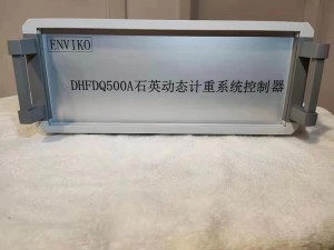
Enviko quartz dynamic weighing system adopts Windows 7 embedded operating system, PC104 + bus extendable bus and wide temperature level components. The system is mainly composed of controller, charge amplifier and IO controller. The system collects data of dynamic weighing sensor (quartz and piezoelectric), ground sensor coil (laser ending detector), axle identifier and temperature sensor, and processes them into complete vehicle information and weighing information, including axle type, axle number, wheelbase, tire number, axle weight, axle group weight, total weight, overrun rate, speed, temperature, etc. It supports the external vehicle type identifier and axle identifier, and the system automatically matches to form a complete vehicle information data upload or storage with vehicle type identification.
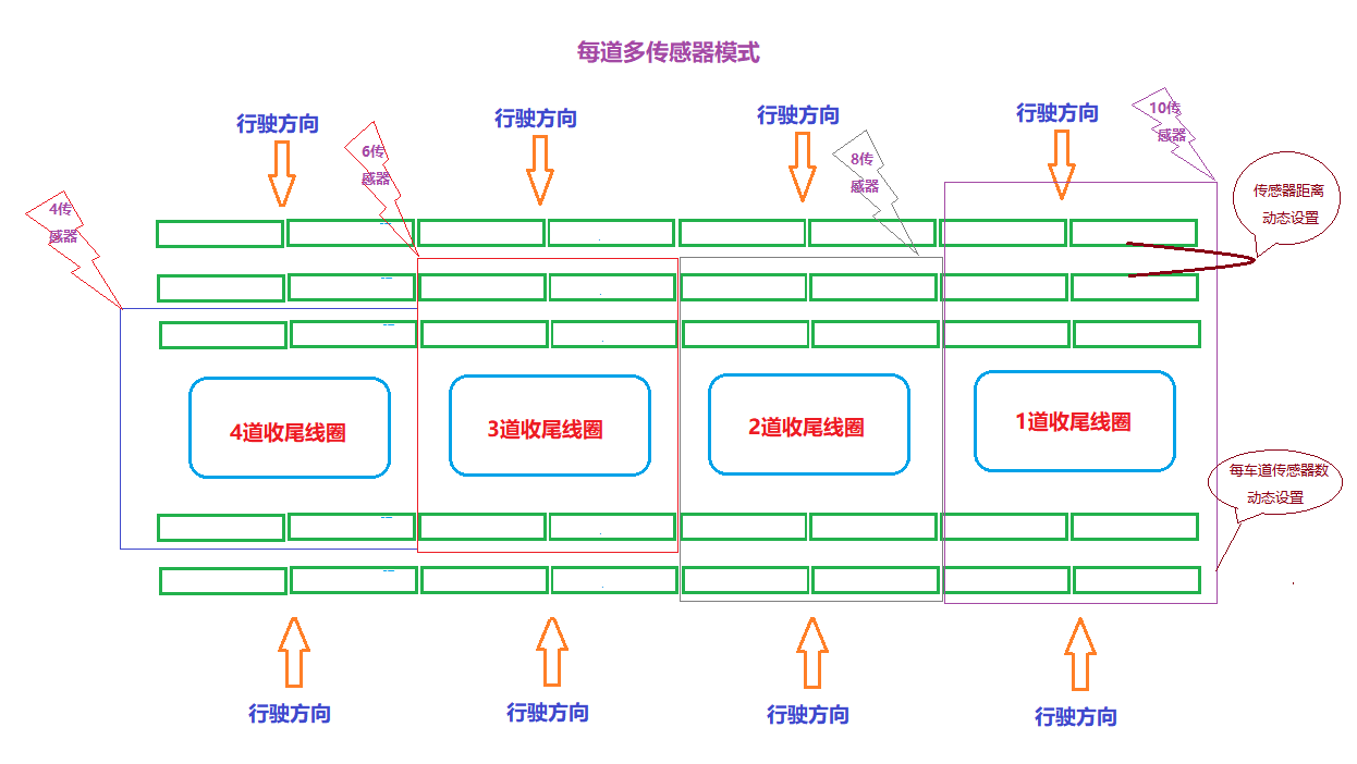
The system supports multiple sensor modes. The number of sensors in each lane can be set from 2 to 16. The charge amplifier in the system supports imported, domestic and hybrid sensors. The system supports IO mode or network mode to trigger the camera capture function, and the system supports the capture output control of front, front, tail and tail capture.
The system has the function of state detection, the system can detect the status of main equipment in real time, and can automatically repair and upload information in case of abnormal conditions; the system has the function of automatic data cache, which can save the data of vehicles detected for about half a year; the system has the function of remote monitoring, Support remote desktop, Radmin and other remote operation, support remote power-off reset; the system uses a variety of protection means, including three-level WDT support, FBWF system protection, system curing antivirus software, etc.
Technical parameters
| power | AC220V 50Hz |
| speed range | 0.5km/h~200km/h |
| sale division | d =50kg |
| axle tolerance | ±10% constant speed |
| vehicle accuracy level | 5 class,10class ,2 class(0.5km/h~20km/h) |
| Vehicle separation accuracy | ≥99% |
| Vehicle recognition rate | ≥98% |
| axle load range | 0.5t~40t |
| Processing lane | 5 lanes |
| Sensor channel | 32channels, or to 64 channels |
| Sensor layout | Support multiple sensor layout modes, each lane as 2pcs or 16pcs sensor to sent ,support a variety of pressure sensors. |
| Camera trigger | 16channel DO isolated output trigger or network trigger mode |
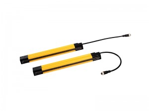
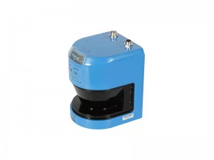
| Ending detection | 16channel DI isolation input connect coil signal, laser ending detection mode or auto ending mode. |
| System software | Embedded WIN7 operating system |
| Axle identifier access | Support a variety of wheel axle recognizer (quartz, infrared photoelectric, ordinary) to form complete vehicle information |
| Vehicle type identifier access | it supports vehicle type identification system and forms complete vehicle information with length, width and height data. |
| Support bidirectional detection | Support forward and reverse bidirectional detection. |
| Device interface | VGA interface, network interface, USB interface, RS232, etc |
| State detection and monitoring | Status detection: the system detects the status of main equipment in real time, and can automatically repair and upload information in case of abnormal conditions. |
| Remote monitoring: support remote desktop, Radmin and other remote operations, support remote power-off reset. | |
| Data storage | Wide temperature solid state hard disk, support data storage, logging, etc. |
| System protection | Three level WDT support, FBWF system protection, system curing antivirus software. |
| System hardware environment | Wide temperature industrial design |
| Temperature control system | The instrument has its own temperature control system, which can monitor the temperature status of the equipment in real time and dynamically control the fan start and stop of the cabinet |
| Use environment (wide temperature design) | Service temperature: - 40 ~ 85 ℃ |
| Relative humidity: ≤ 85% RH | |
| Preheating time: ≤ 1 minute |
Device interface
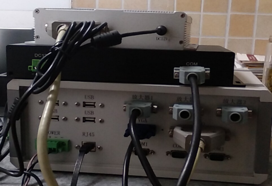
1.2.1 system equipment connection
The system equipment is mainly composed of system controller, charge amplifier and IO input / output controller
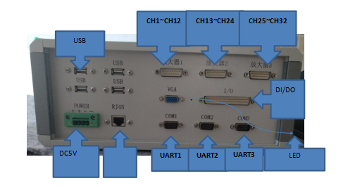
1.2.2 system controller interface
The system controller can connect 3 charge amplifiers and 1 IO controller, with 3 rs232/rs465, 4 USB and 1 network interface.
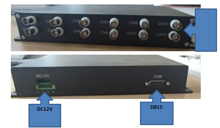
1.2.1 amplifier interface
The charge amplifier supports 4, 8, 12 channels (optional) sensor input, DB15 interface output, and the working voltage is DC12V.
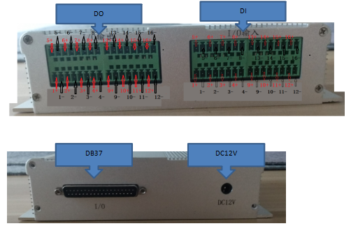
1.2.1 I / O controller interface
IO input and output controller, with 16 isolated input, 16 isolation output, DB37 output interface, Working Voltage DC12V.
system layout
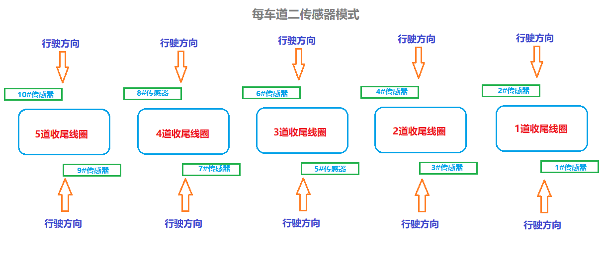
2.1 sensor layout
It supports multiple sensor layout modes such as 2, 4, 6, 8 and 10 per lane, supports up to 5 lanes, 32 sensor inputs (which can be expanded to 64), and supports forward and reverse two-way detection modes.
DI control connection
16 channels of DI isolated input, supporting coil controller, laser detector and other finishing equipment, supporting Di mode such as optocoupler or relay input. The forward and reverse directions of each lane share one ending device, and the interface is defined as follows;
| Ending lane | DI interface port number | note |
| No 1 lane(forward ,reverse) | 1+、1- | If the ending control device is optocoupler output, the ending device signal should correspond to the + and - signals of IO controller one by one. |
| No 2 lane(forward ,reverse) | 2+、2- | |
| No 3 lane(forward ,reverse) | 3+、3- | |
| No 4 lane(forward ,reverse) | 4+、4- | |
| No 5 lane(forward ,reverse) | 5+、5- |
DO control connection
16 channel do isolated output, used to control the trigger control of the camera, support level trigger and falling edge trigger mode. The system itself supports forward mode and reverse mode. After the trigger control end of forward mode is configured, the reverse mode does not need to be configured, and the system switches automatically. The interface is defined as follows:
| Lane number | Forward trigger | Tail trigger | Side direction trigger | Tail side direction trigger | Note |
| No1 lane (forward) | 1+、1- | 6+、6- | 11+、11- | 12+、12- | The trigger control end of the camera has a + - end. The trigger control end of the camera and the + - signal of IO controller should correspond one by one. |
| No2 lane(forward) | 2+、2- | 7+、7- | |||
| No3 lane(forward) | 3+、3- | 8+、8- | |||
| No4 lane(forward) | 4+、4- | 9+、9- | |||
| No5 lane(forward) | 5+、5- | 10+、10- | |||
| No1 lane(reverse) | 6+、6- | 1+、1- | 12+、12- | 11+、11- |
system usage guide
3.1 Preliminary
Preparation before instrument setting.
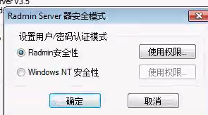
3.1.1 set Radmin
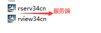
1) Check if Radmin server is installed on the instrument (factory instrument system). If it is missing, please install it
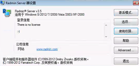
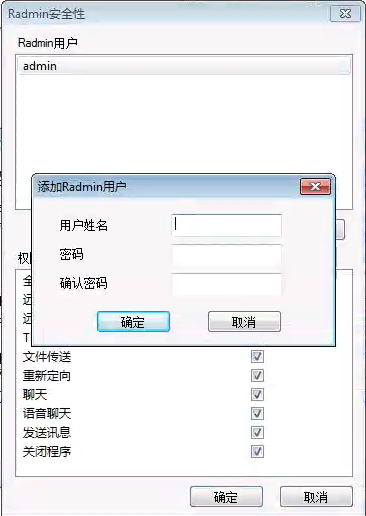
2)Set Radmin, add account and password
3.1.2 system disk protection
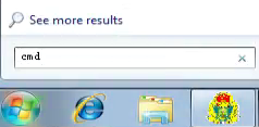
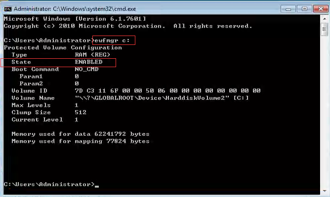
1)Running the CMD instruction to enter the DOS environment.
2)Query EWF protection status (type EWFMGR C: enter)
(1)At this time, EWF protection function is on(State = ENABLE)
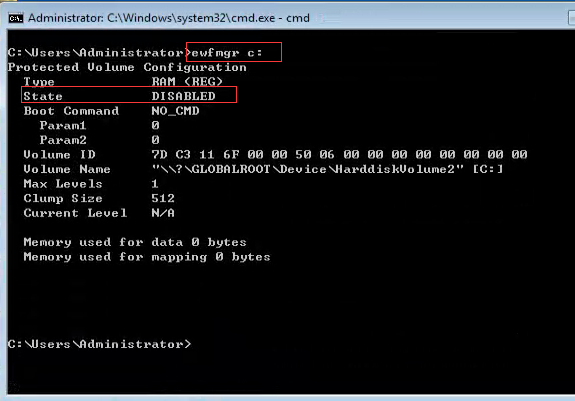
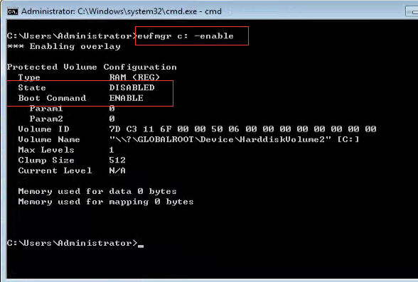
(Type EWFMGR c: -communanddisable -live enter), and state is disabled to indicate that EWF protection is off
(2)At this time, EWF protection function is closing (state = disable), no subsequent operation is required.
(3) After changing the system settings, set EWF to enable
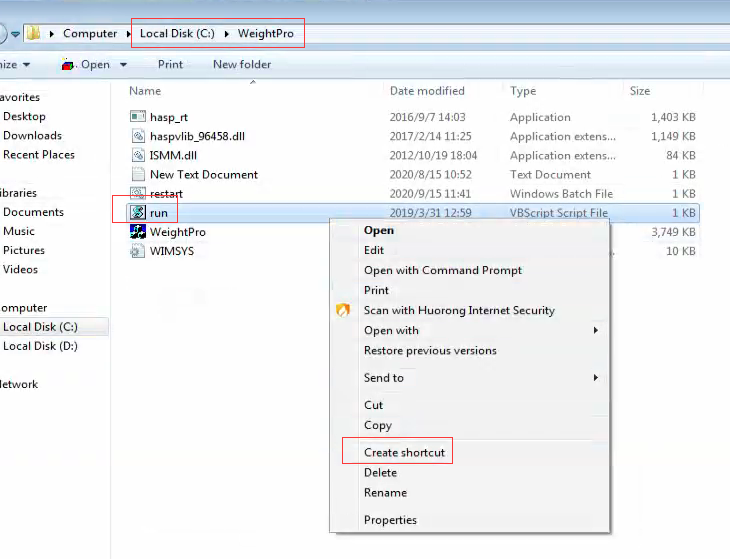
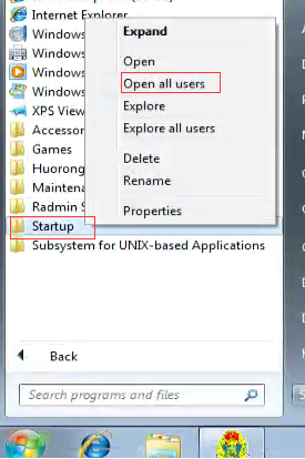
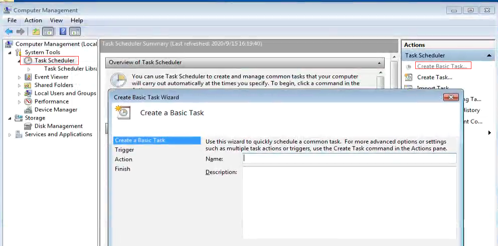
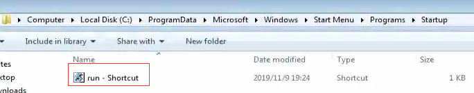
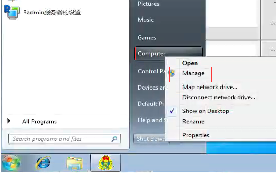
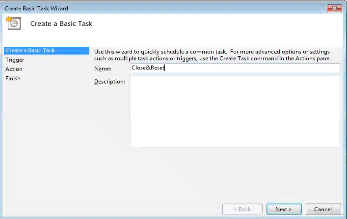
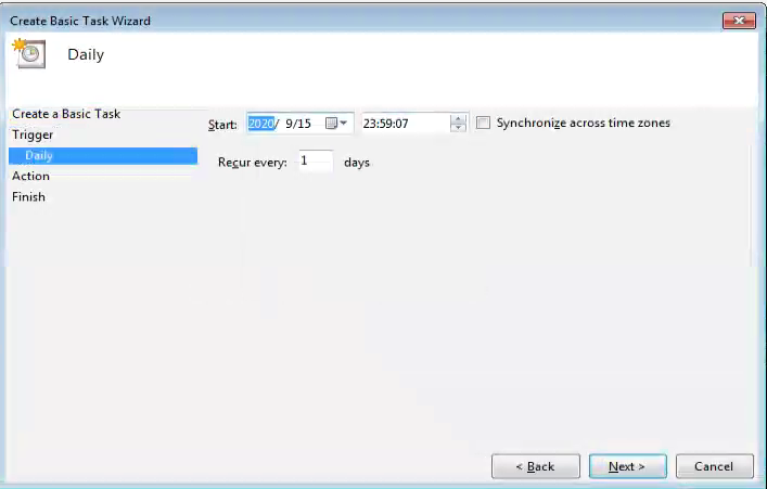
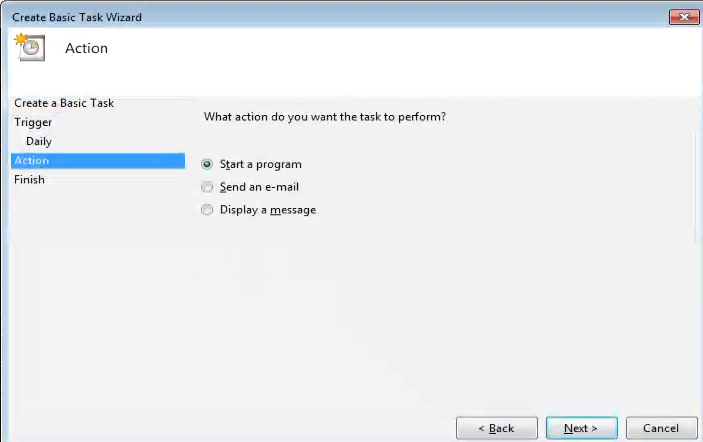
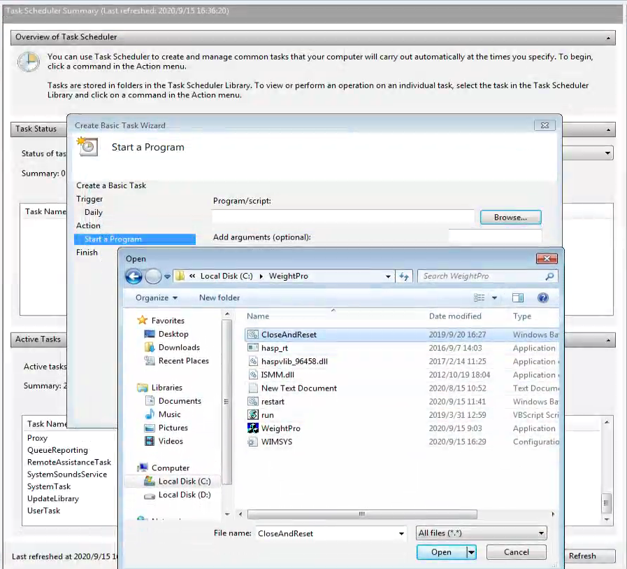
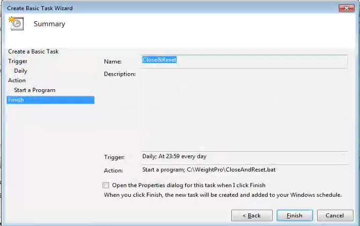
3.1.3 Create auto start shortcut
1)Create a shortcut to run.
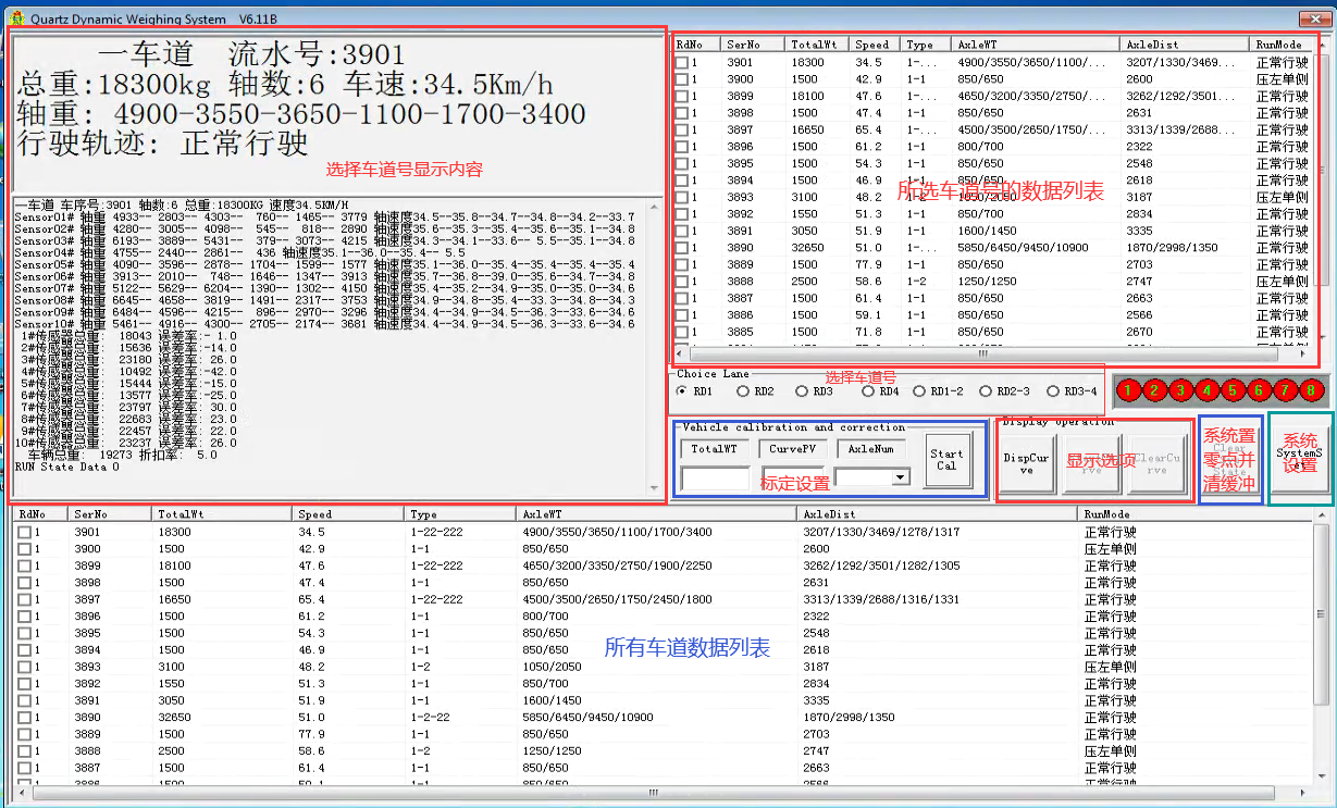
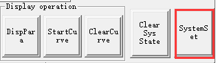
3.2 Introduction to system interface
3.3 System parameter setting
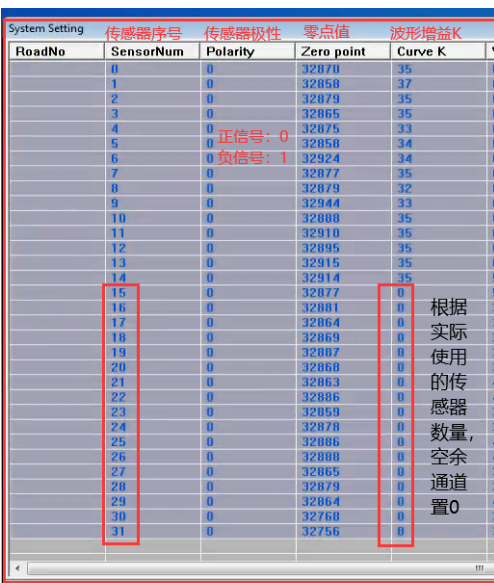
3.3.1 System initial parameter setting.
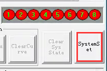
(1)Enter the system settings dialog box
(2) Setting parameters
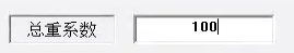
a.Set the total weight coefficient as 100
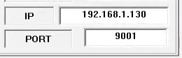
b.Set IP and port number
c.Set the sample rate and channel
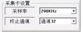
Note: when updating the program, please keep the sampling rate and channel consistent with the original program.
d.Parameter setting of spare sensor
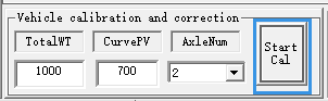
4. Enter the calibration setting
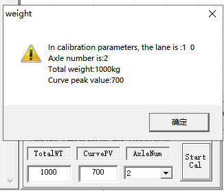
5.When the vehicle passes through the sensor area evenly (the recommended speed is 10 ~ 15km / h), the system generates new weight parameters
6.Reload new weight parameters.
(1)Enter system settings.
(2)Click Save to exit.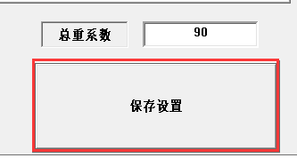
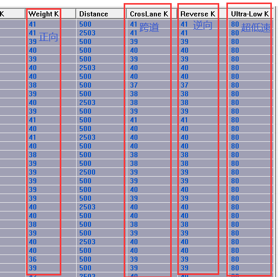
5. Fine tuning of system parameters
According to the weight generated by each sensor when the standard vehicle passes through the system, the weight parameters of each sensor are adjusted manually.
1.Set up the system.
2.Adjust the corresponding K-factor according to the driving mode of the vehicle.
They are forward, cross channel, reverse and ultra-low speed parameters.
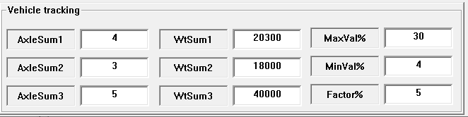
6.System detection parameter setting
Set the corresponding parameters according to the system detection requirements.
System communication protocol
TCPIP communication mode, sampling XML format for data transmission.
- Vehicle entering: the instrument is sent to the matching machine, and the matching machine does not reply.
| Detective head | Data body length (8-byte text converted to integer) | Data body (XML string) |
| DCYW | <root type=”carcome”>
<data deviceno=Instrument number roadno=Road no recno=Data serial number /> </root> |
- Vehicle leaving: the instrument is sent to the matching machine, and the matching machine does not reply
| head | (8-byte text converted to integer) | Data body (XML string) |
| DCYW | <root type=”cargo”>
<data deviceno=Instrument number roadno=Road No recno= Data serial number /> </root> |
- Upload of weight data: the instrument is sent to the matching machine, and the matching machine does not reply.
| head | (8-byte text converted to integer) | Data body (XML string) |
| DCYW | <root type=”weight”>
<data deviceno= Instrument number roadno=Road no: recno=Data serial number kroadno=Cross the road sign; do not cross the road to fill in 0 speed=speed; Unit kilometer per hour weight= total weight: unit: Kg axlecount=Number of axes; temperature= temperature; maxdistance=The distance between the first axis and the last axis, in millimetres axlestruct=Axle structure: for example, 1-22 means single tire on each side of the first axle, double tire on each side of the second axle, double tire on each side of the third axle, and the second axle and the third axle are connected weightstruct=Weight structure: for example, 4000809000 means 4000kg for the first axle, 8000kg for the second axle and 9000kg for the third axle distancestruct=Distance structure: for example, 40008000 means that the distance between the first axis and the second axis is 4000 mm, and the distance between the second axis and the third axis is 8000 mm diff1=2000 is the millisecond difference between the weight data on the vehicle and the first pressure sensor diff2=1000 is the millisecond difference between the weight data on the vehicle and the ending length=18000; vehicle length; mm width=2500; vehicle width; unit: mm height=3500; vehicle height; unit mm /> </root> |
- Equipment status: the instrument is sent to the matching machine, and the matching machine does not reply.
| Head | (8-byte text converted to integer) | Data body (XML string) |
| DCYW | <root type=”weightstatus”>
<data deviceno=Instrument number code=”0” Status code, 0 indicates normal, other values indicate abnormal msg=”” State description /> </root> |
Enviko has been specializing in Weigh-in-Motion Systems for over 10 years. Our WIM sensors and other products are widely recognized in the ITS industry.