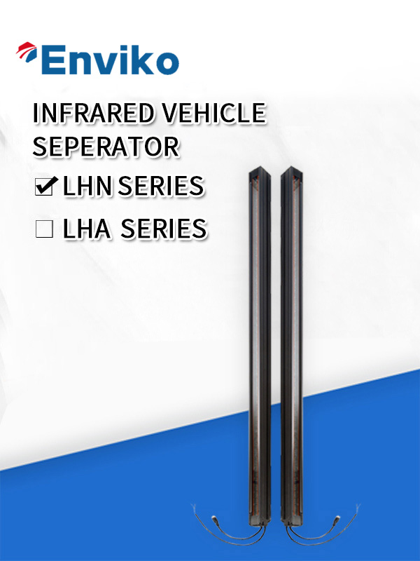
Infrared Vehicle Separators


Short Description:
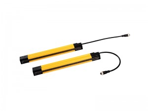
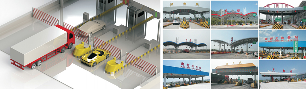
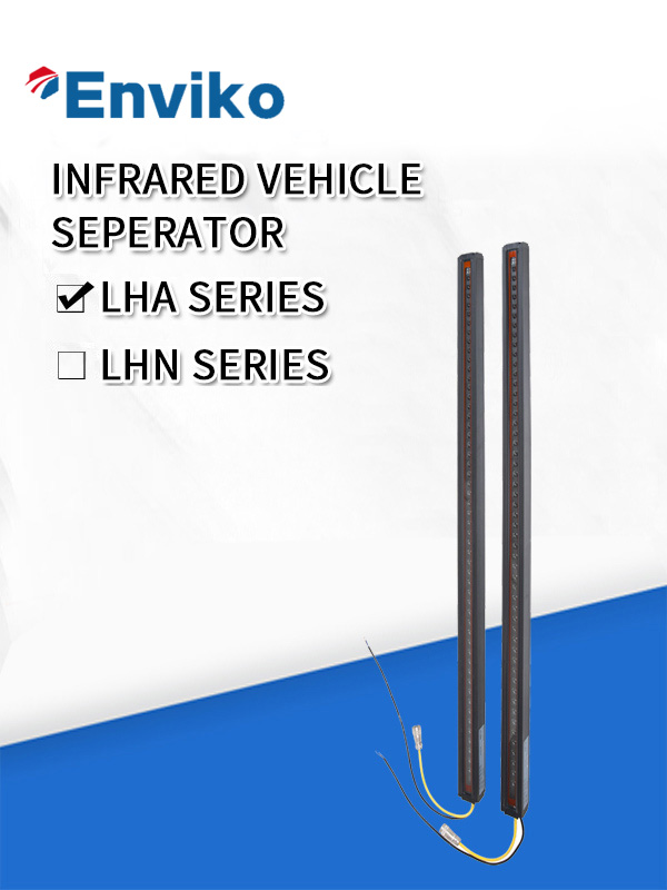
ENLH series infrared vehicle separator is a dynamic vehicle separation device developed by Enviko using infrared scanning technology. This device consists of a transmitter and a receiver, and works on the principle of opposing beams to detect the presence and departure of vehicles, thereby achieving the effect of vehicle separation. It features high accuracy, strong anti-interference capability, and high responsiveness, making it widely applicable in scenarios such as general highway toll stations, ETC systems, and weigh-in-motion (WIM) systems for highway toll collection based on vehicle weight.
Product Detail
Product features
| Features | Description |
| Receiving beam strength detection | 4 levels of beam strength are set up, it is convenient for field installation and maintenance. |
| Diagnosis function | Diagnostic LEDs provide a simple means of monitoring sensor performance. |
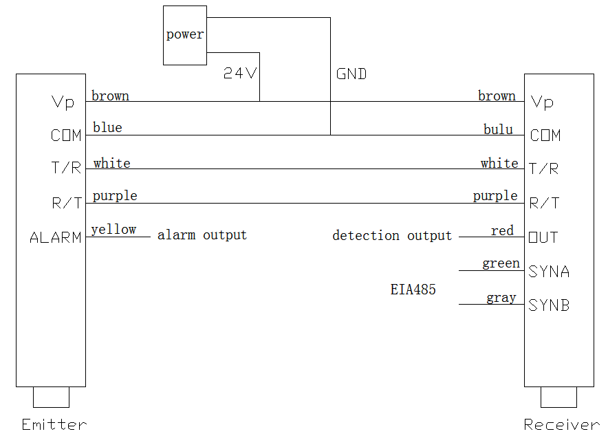
| Outputs | Two discrete outputs (Detection output and alarm output, NPN/PNP optional), plus EIA-485 serial communication. |
| Shielding function | Can automatically detect the failures of the emitter or the receiver and pollution state of the lens, it can still work in the state of failures, at the mean time send out warning instructions and alarm outputs. |
1.1 Product components
The products include the following components:
● Emitter and receiver;
● One 5-core (emitter) and one 7-core (receiver) quick-disconnect cables;
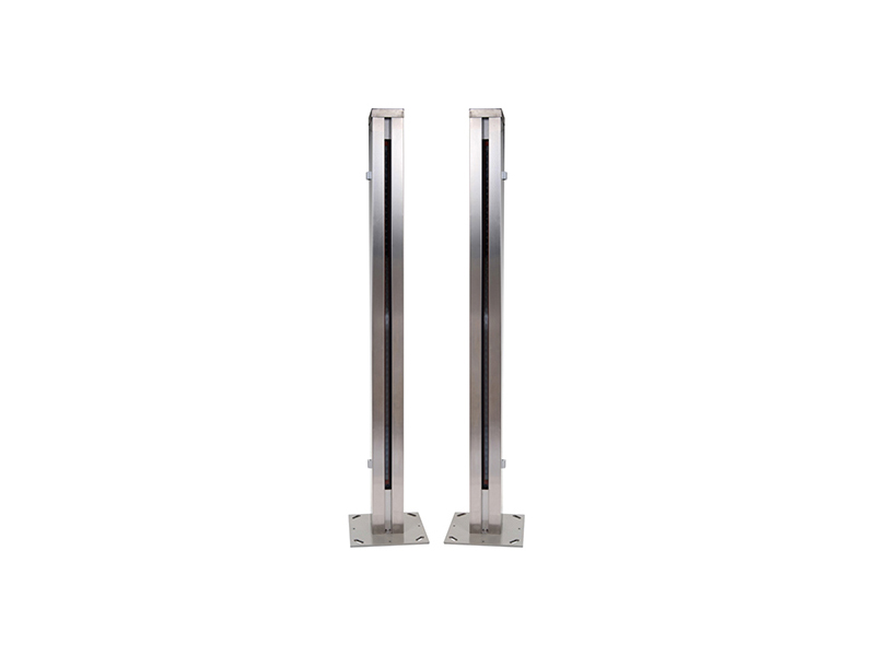
● Protected cover;
1.3 Product working principle
The product is mainly consist of a receiver and an emitter, using the principle of counter shoot.
The receiver and the emitter have the same quantity of LED and photoelectric cell, the LED in emitter and photoelectric cell in receiver is synchronous touched off, when the light is block off, the system makes the output.
Product specifications
| Contents | Specifications |
| Optical axis number(beam); optical axis spacing; scanning length | 52; 24mm; 1248mm |
| Effective detection length | 4 ~ 18m |
| Minimum object sensitivity | 40mm(straight scan) |
| Supply voltag | 24v DC±20%; |
| Supply current | ≤ 200mA; |
| Discrete outputs | Transistor PNP/NPN available,detection outputs and alarm outputs,150mA max.(30v DC) |
| EIA-485 outputs | EIA-485 serial communication enables a computer to process scan data and system status. |
| Indicator light outputs | Working status light (red), power light (red), receiving beam strength light (red and yellow each) |
| Response time | ≤ 10ms(straight scan) |
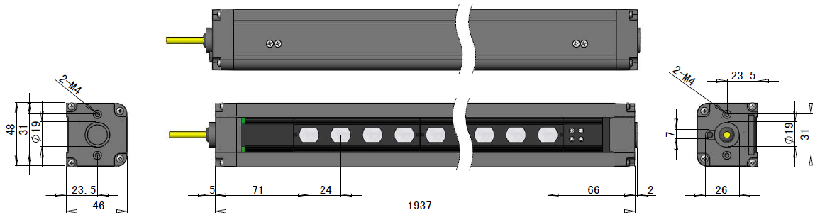
| Dimensions (length * width * height) | 1361mm × 48mm × 46mm |
| Operating condition | Temperature:-45℃ ~ 80℃,maximum relative humidity:95% |
| Construction | aluminum housing with black anodized finish; toughened glass windows |
| Environmental rating | IEC IP67 |
Indicator light instruction
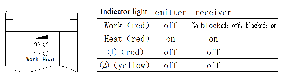
LED lights are utilized to indicate the working status and the failure status of the products, the emitter and the receiver have the same amount of indicator light. The LED lights are set up at the top of the emitter and the receiver, which is shown in figure 3.1
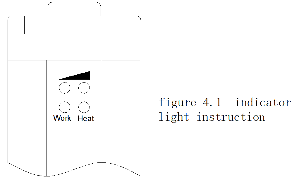
Diagram 3.1 indicator light instruction (working status; power light)
|
Indicator light |
emitter |
receiver |
| Work(red):Working status light | on:light screen works abnormally *off:light screen works normally | on:light screen is blocked **off:light screen is not blocked |
| Heat (red):Power light | on:receiving beam is strong (the excessive gain is more than 8)flashing:receiving beam is faint (the excessive gain is less than 8) | |
Note: * when light screen works abnormally, alarm outputs send out; ** when the number of optical axis that are blocked is larger than the number of beam set, detection outputs send out.
Diagram 3.2 indicator light instruction(receiving beam strength/ light)
|
Indicator light |
Emitter and receiver |
remarking |
| (①Red, ②yellow) | ①Off,②off:excessive gain:16 | 1 at the length of 5m, the excessive gain is more than 16; at the maximum detection length, the excessive gain is 3.2 when the excessive gain is less than 8, the power light is flashing. |
| ①on,②off:excessive gain: 12 | ||
| ①off,②on:excessive gain :8 | ||
| ①on,②on:excessive gain :4 |
Product dimensions and hookup
4.1 product dimensions is shown in figure 4.1;
4.2 product hookup is shown in figure 4.2
Detection instructions
5.1 Connection
First, set up the receiver and the emitter of the light screen according to the figure 4.2, and make sure the connection is right (power off when connecting), then, set the emitter and the receiver face to face at the effective distance.
5.2 Alignment
Turn on the power (24v DC), after two flashing of the light screen indicator light, if the power light (red) of the emitter and the receiver is on, while the working status light (red) is off, the light screen is aligned.
If the working status light (red) of the emitter is on, the emitter and (or) the receiver may have malfunction, and needed to be repaired back to the factory.
If the working status light (red) of the receiver is on, the light screen might not be aligned, move or rotate the receiver or emitter slowly and observe, until the working status light of the receiver is off (if it cannot be aligned after a long time, it means to be repaired back to the factory).
Warning: no objects allowed during the process of alignment.
The receiving beam strength light (red and yellow each) of the emitter and the receiver is related to the real working distance, the customers need to regulate based on actual use. More details in diagram 3.2.
5.3 Light screen detection
The detection should be operated within the effective distance and the detection height of the light screen.
Using the objects whose size is 200*40mm to detect the light screen, the detection could be operated anywhere between the emitter and the receiver, commonly at receiver end, which is easier to observe.
During the detection, detect three times in constant speed (>2cm/s) about the object. (long side is perpendicular to the beam, horizontal center, top-down or bottom-up)
During the process, the working status light (red) of the receiver should be on all the time, the statement that corresponds to detection outputs should not change.
The light screen is working normally when meeting the above requirements.
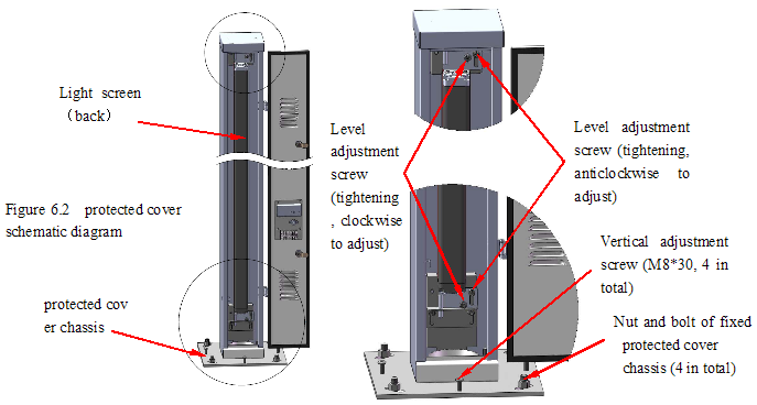
Adjustment
If light screen is Not in the best working condition (see figure 6.1 and diagram 6.1), it must be adjusted. See figure 6.2.
1, The horizontal direction: adjust the protected cover: 4 loosen nut of fixed protected cover chassis, manual rotation of the protected cover;
Adjust the light screen: unclip the right level adjustment screw, and tighten the left level adjustment screw clockwise to adjust the light screen. On the contrary, reversible adjust light screen. Pay attention to adjust the amount of left, right screw;
2, The vertical direction: 4 loosen nut of fixed protected cover chassis, 4 vertical adjustment screw to adjust the installation on the chassis;
3, To observe the indicator of the state, to the light screen in the best working condition, tighten the chassis fixing nuts and all loose screws.
Factory set
The following parameters can be changed through EIA485 serial interface, the factory set is:
1 When triggered outputs, continuous cover optical axis number N1=5;
2 When continuous N1-1 optical axis (minimum 3) are occluded, fault alarm time: T = 6(60s);
3 Detection output type: NPN normally open;
4 Alarm output type: NPN normally open;
5 Scanning approach: straight scan;
Serial communication interface
8.1 Serial communication interface
● EIA485serial interface,half-duplex asynchronous communication;
● Baud rate:19200;
● Character format: 1 start bit, 8 data bits, 1 stop bit, no parity, send and receive data from the low start
8.2 Send and receive data format
● Data format:all the data is hexadecimal format, every sending and receiving data include: 2 command byte value, 0~multiple data bytes, 1 check code byte;
● 4 sending and receiving commands in total, as shown in diagram 8.1
Diagram 8.1
Order value
(hexadecimal) definition Data format(for serial interface light screen)
receive(hexadecimal) send(hexadecimal)*
0x35、0x3A Light screen state information set 0x35,0x3A,N1, T,B,CC 0x35,0x3A,N,N1,T,B,CC
0x55、0x5A Light screen state information transmit 0x55,0x5A,CC 0x55,0x5A,N,N1,T,B,CC
0x65、0x6A Light screen beam information transmit (intermittent) 0x65,0x6A,n,CC 0x65,0x6A,n,D1,D2,…,Dn,CC
0x95、0x9A Light screen beam information transmit (continuous) 0x95,0x9A,n,CC 0x95,0x9A,n,D1,D2,…,Dn,CC
N1 When has triggered outputs, the number that continuous keep out the beam, 0 < N1 < 10 and N1 < N;
T The time that continuous N1-1 beam of light to be kept out(10*T second),alarm outputs when over time, 0< T <= 20;
B Detection output(bit 0 , the receiver)、0(bit 1)、alarm output(bit 2, the emitter)open/close sign,0 open regularly,1 close regularly. Scan type sign(bit 3),0 straight scan,1 cross scan. 0x30 ~ 0x3F.
N The total number of the beam;
n The number of sections that required to transmit the information of the beam (8 beams make up one section), 0 < n <= N/8, when N/8 has remnant, add one section;
D1,…,Dn Information of every section of beam(for every beams,conduction is 0,cover is 1);
CC 1 Byte check code, which is the sum of all the number before(hexadecimal) and eliminate the high 8
8.3 Instruction of sending and receiving data
1 The initialization settings of the light screen is serial communication receiving mode, prepared for receiving data. Every time receives one data, according to the commandment of receiving data, set up data content and set serial communication mode to sending, proceeding data sent. After the data is sent, set serial communication mode to receiving again.
2 Only when receiving the right data, the process of sending data starts. The wrong data received include: wrong check code, wrong order value(not one of 0x35、0x3A / 0x55、0x5A / 0x65、0x6A / 0x95、0x9A);
3 The initialization settings of the customer’s system is required to be serial communication sending mode, every time after the data is sent, set serial communication mode to receive immediately, prepare for receiving the data that light screen sent.
4 When the light screen receives the data that sent by costumer’s system, send data after this scanning cycle. Therefore, for the customer’s system, after sending data every time, normally, should consider 20~30ms waiting for receiving data.
5 For the commandment of light screen state information set(0x35、0x3A),due to the need to write the EEPROM,there will be more time that used for sending data to be spent. For this command, recommend the customer to consider about 1s waiting for receiving data.
6 Under normal condition, the customer system would use light screen beam information transmission command (0x65、0x6A/ 0x95、0x9A)frequently, but light screen state information setting(0x35、0x3A) and transmission command(0x55、0x5A)are only used when required. Therefore, if it is not necessary, highly recommend not to use in the customer system (especially light screen state information setting command).
7 As the mode of the EIA485 serial interface is half-duplex asynchronous, the working principle of its intermittent sending(0x65、0x6A) and continuous sending(0x95、0x9A)is in the following words:
● Intermittent sending:During the initialization, set the serial interface to receive, when the command from customer system is received, set the serial interface to transmit. Then send data based on the command received, after sending the data, the serial interface will be reset to receive.
● Continuous sending:when the command value received is 0x95、0x9A, start continuous sending light screen beam information.
● At the condition of continuous sending, if anyone of the optical axis in the light screen is kept out, send out serial data under the circumstance that every scanning circle is over while the serial interface is available, at the meanwhile, the serial interface will be set to transmit.
● At the condition of continuous sending, if no optical axis in the light screen is kept out and the serial interface is available (after transmitting this data), the serial interface will be set to receive, waiting for receiving data.
● Warning: at the condition of continuous sending, customer system is always the side that receiving data, when transmitting is needed, it can only proceed under the circumstance that the light screen is not kept out and must be finished in 20~30ms after the data is received, otherwise, it could cause serial communication problems that cannot be predicted, and it could cause damage of the serial interface, when it is worse.
Instructions of Light-Screen and how to communicate with a PC
9.1 Overview
Light-Screen is used to set up communication between LHAC series light screen and PC, people can set and detect the working status of light screen through Light-Screen.
9.2 Installation
1 Installation requirements
● Windows 2000 or XP operating system in Chinese or English;
● Have RS232 serial interface (9-pin);
2 Installation steps
● Open the folders: PC communication software\installer;
● Click the install file, install Light-Screen;
● If it already has Light-Screen,install executes delete operations firstly, then reinstall the software
● During the installation, you need to specify the installation directory first, then click Next to install
9.3 Operation instructions
1 Click “start”, find “program(P)\Light-Screen\Light-Screen”, make Light-Screen into operation;
2 After operating Light-Screen,first appear the interface shown in figure 9.1, the left interface; click the interface or wait 10 seconds, the picture on the right of figure 9.1 appears.
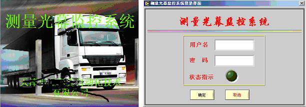
3 sign in the user name: abc, passwords: 1, then click “confirm”, enter the working interface of Light Screen, as shown in figure 9.2 and figure 9.3.
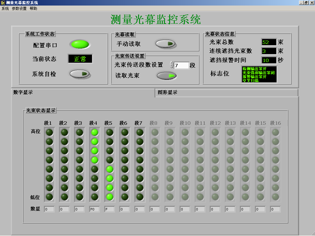
Figure 9.2 Digital display working interface
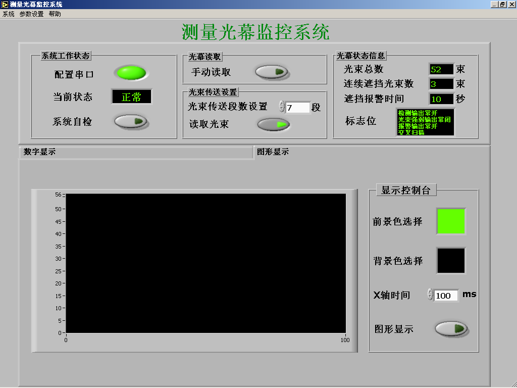
Figure 9.3 Graphic display working interface
4 The display working interface is used to display the working information and status information of the light screen, more details in the following words:
● System working state:the current statebox indicates whether the serial communication is normal or not,click system self-checkbutton, proceed a serial test;
● Light screen read:click manual read button, read the light screen status information once;
● Beam transmission settings:beam transmission sections set sets up the section number of transmitting beam, when the read beam button is on, continuous send beam information;
● Light screen status information:display the light screen’s total number of beam, the number of continuous beam that blocked, the block alarm time, (the fault alarm time of less than continuous N1-1 beam that is blocked), marks such as detection outputs, beam strength outputs (unused), fault alarm outputs regularly open/close sign and scanning type (straight scanning/cross scanning), etc
● Digital display (figure 9.2):indicator light (arrange by section, the bottom optical axis is the first)indicates every beam’s statement, light on when it is blocked, light off when it is not blocked.
● Graphic display (figure 9.3): display the shape of the objects that pass through the light screen in a period of time.
● Graphic display console:choose the color of the graphics (the foreground selection- the background color of the graphics(the background selection-), the time width of the display window( time of X axis-X), etc. when the graphic display( button is on, start data collection and display.
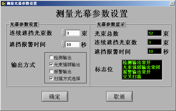
5 When making choice parameter settings/system parameter menu, display parameter setting interface (figure 9.4), in order to set the working parameters of the light screen, more details are in the following words:
● Light screen parameters set:set up the number of beam that is kept out continuously, block alarm time, the output modeof every marks, etc. Among them: signs such as detection outputs beam strength outputs (unused), fault alarm outputs are regularly closed when selected ( have√ inside the box), the scanning type is cross scanning when selected.;
● Light screen parameters display: display the marks of the light screen, such as the total number of beam, the number of beam that is blocked continuously, the block alarm time, detection outputs, beam strength outputs (unused), fault alarm outputs regularly open/close sign and scanning type (cross scan/straight scan), etc.
● After the set up of the light screen parameters, click confirm button, display reset light screen parameters box, click the confirm button of the box, to set the light curtain parameters, click cancel button, if you don’t want to set the parameters.
● Click the cancel button on the parameter setup interface to quit this interface.
The communication between the light screen and PC
10.1 The connection between the light screen and PC
Use EIA485RS232 converter to connect, connect the 9-core socket of the converter with the 9-pin serial interface of PC, the other end of the converter connects with EIA485 serial interface line (2 lines)of the light screen (shown in figure 4.2). Connect the TX+ with SYNA (green line) of the receiver of the light screen, connect TX- with the SYNB (grey line) of the receiver of the light curtain.
10.2 The communication between the light screen and PC
1 Connection: connect the emitter and the receiver as shown in figure 5.2, and make sure the connection is right (power off while connecting the cables), set up the emitter and the receiver face to face and make alignment.
2 Power on the light screen:turn on the power supply (24V DC), waiting for the light screen into normal working condition (more details in the section 6, detection instruction)
3 Communication with PC: operate the program Light-Screen, according to section 9, instructions of Light Screen and how to communicate with a PC.
10.3 Status detection and parameters setup of the light screen
1 Detect the working status of the light screen through digital display interface: using the object whose size is 200*40mm moving on every optical axis, the indicator light on the digital display interface is on or off correspondingly (the read beam(读取光束)button should be lighten up during the operation)
2 When using parameters setup interface to set the parameters of the light screen, you should pay attention to section 9, instructions of Light Screen and how to communicate with a PC
Enviko has been specializing in Weigh-in-Motion Systems for over 10 years. Our WIM sensors and other products are widely recognized in the ITS industry.