
CET-DQ601B Charge Amplifier

Short Description:
Enviko charge amplifier is a channel charge amplifier whose output voltage is proportional to the input charge. Equipped with piezoelectric sensors, it can measure the acceleration, pressure, force and other mechanical quantities of objects.
It is widely used in water conservancy, power, mining, transportation, construction, earthquake, aerospace, weapons and other departments. This instrument has the following characteristic.
Product Detail
Function overview
CET-DQ601B
charge amplifier is a channel charge amplifier whose output voltage is proportional to the input charge. Equipped with piezoelectric sensors, it can measure the acceleration, pressure, force and other mechanical quantities of objects. It is widely used in water conservancy, power, mining, transportation, construction, earthquake, aerospace, weapons and other departments. This instrument has the following characteristic.
1).The structure is reasonable, the circuit is optimized, the main components and connectors are imported, with high precision, low noise and small drift, so as to ensure the stable and reliable product quality .
2). By eliminating the attenuation input of the equivalent capacitance of the input cable, the cable can be extended without affecting the measurement accuracy.
3).output 10VP 50mA.
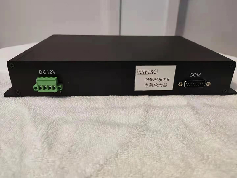
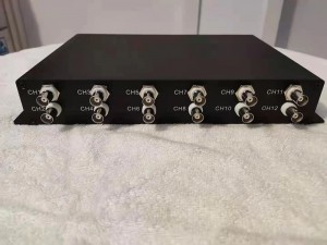
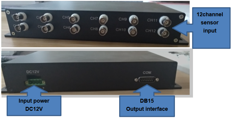
4).Support 4,6,8,12 channel(optional), DB15 connect output, working voltage:DC12V.
Work principle
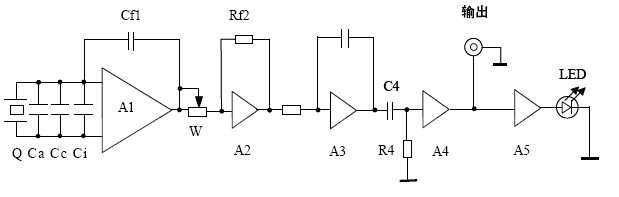
CET-DQ601B charge amplifier is composed of charge conversion stage, adaptive stage, low pass filter, high pass filter, final power amplifier overload stage and power supply. Th:
1).Charge conversion stage: with operational amplifier A1 as the core.
CET-DQ601B charge amplifier can be connected with piezoelectric acceleration sensor, piezoelectric force sensor and piezoelectric pressure sensor. The common characteristic of them is that the mechanical quantity is transformed into a weak charge Q which is proportional to it, and the output impedance RA is very high. The charge conversion stage is to convert the charge into a voltage (1pc / 1mV) which is proportional to the charge and change the high output impedance into low output impedance.
Ca---The capacitance of the sensor is usually several thousand PF, 1 / 2 π Raca determines low frequency lower limit of sensor.
Cc-- Sensor output low noise cable capacitance.
Ci--Input capacitance of operational amplifier A1, typical value 3pf.
The charge conversion stage A1 adopts American wide-band Precision Operational Amplifier with high input impedance, low noise and low drift. The feedback capacitor CF1 has four levels of 101pf, 102pf, 103pf and 104pf. According to Miller's theorem, the effective capacitance converted from the feedback capacitance to the input is: C = 1 + kcf1. Where k is the open-loop gain of A1, and the typical value is 120dB. CF1 is 100pF (minimum) and C is about 108pf. Assuming that the input low noise cable length of the sensor is 1000m, the CC is 95000pf; Assuming that the sensor CA is 5000pf, the total capacitance of caccic in parallel is about 105pf. Compared with C, the total capacitance is 105pf / 108pf = 1 / 1000. In other words, the sensor with 5000pf capacitance and 1000m output cable equivalent to feedback capacitance will only affect the accuracy of CF1 0.1%. The output voltage of the charge conversion stage is the output charge of the sensor Q / feedback capacitor CF1, so the accuracy of the output voltage is only affected by 0.1%.
The output voltage of the charge conversion stage is Q / CF1, so when the feedback capacitors are 101pf, 102pf, 103pf and 104pf, the output voltage is 10mV / PC, 1mV / PC, 0.1mv/pc and 0.01mv/pc respectively.
2).Adaptive level
It consists of operational amplifier A2 and sensor sensitivity adjusting potentiometer W. The function of this stage is that when using piezoelectric sensors with different sensitivities, the whole instrument has a normalized voltage output.
3).low pass filter
The second-order Butterworth active power filter with A3 as the core has the advantages of less components, convenient adjustment and flat passband, which can effectively eliminate the influence of high-frequency interference signals on useful signals.
4).High pass filter
The first-order passive high pass filter composed of c4r4 can effectively suppress the influence of low-frequency interference signals on useful signals.
5).Final power amplifier
With A4 as the core of gain II, output short circuit protection, high precision.
6). Overload level
With A5 as the core, when the output voltage is greater than 10vp, the red LED on the front panel will flash. At this time, the signal will be truncated and distorted, so the gain should be reduced or the fault should be found.
Technical parameters
1)Input characteristic: maximum input charge ± 106Pc
2)Sensitivity: 0.1-1000mv / PC (- 40 '+ 60dB at LNF)
3)Sensor sensitivity adjustment: three digit turntable adjusts sensor charge sensitivity 1-109.9pc/unit (1)
4)Accuracy:
LMV / unit, lomv / unit, lomy / unit, 1000mV / unit, when the equivalent capacitance of input cable is less than lonf, 68nf, 22nf, 6.8nf, 2.2nf respectively, lkhz reference condition (2) is less than ± The rated working condition (3) is less than 1% ± 2%.
5)Filter and frequency response
a)High pass filter;
The lower limit frequency is 0.3, 1, 3, 10, 30 and loohz, and the allowable deviation is 0.3hz, - 3dB_ 1.5dB; l. 3, 10, 30, 100Hz, 3dB ± LDB, attenuation slope: - 6dB / cot.
b)low pass filter;
Upper limit frequency: 1, 3, lo, 30, 100kHz, BW 6, allowable deviation: 1, 3, lo, 30, 100khz-3db ± LDB, attenuation slope: 12dB / Oct.
6)output characteristic
a)Maximum output amplitude:±10Vp
b)Maximum output current:±100mA
c)Minimum load resistance:100Q
d)Harmonic distortion: less than 1% when the frequency is lower than 30kHz and the capacitive load is less than 47nF.
7)Noise: < 5 U V (the highest gain is equivalent to the input)
8)Overload indication: the output peak value exceeds I ±( At 10 + O.5 FVP, the LED is on for about 2 seconds.
9)Preheating time: about 30 minutes
10)Power supply: AC220V ± 1O%
usage method
1. the input impedance of charge amplifier is very high. In order to prevent the human body or external induction voltage from breaking down the input amplifier, the power supply must be turned off when connecting the sensor to the charge amplifier input or removing the sensor or suspecting the connector is loose.
2. although long cable can be taken, the extension of cable will introduce noise: inherent noise, mechanical motion and induced AC sound of cable. Therefore, when measuring on site, the cable should be low noise and shorten as much as possible, and it should be fixed and far away from large power equipment of power line.
3. the welding and assembly of connectors used on sensors, cables and charge amplifiers are very professional. If necessary, special technicians shall carry out the welding and assembly; Rosin anhydrous ethanol solution flux (welding oil is forbidden) shall be used for welding. After welding, the medical cotton ball shall be coated with anhydrous alcohol (medical alcohol is forbidden) to wipe the flux and graphite, and then dry. The connector shall be kept clean and dry frequently, and the shield cap shall be screwed when not used
4. in order to ensure the accuracy of the instrument, preheating shall be conducted for 15 minutes before measurement. If the humidity exceeds 80% the preheating time should be more than 30 minutes。
5. Dynamic response of output stage: it is mainly shown in the ability to drive capacitive load, which is estimated by the following formula: C = I / 2 л In the vfmax formula, C is the load capacitance (f); I output stage output current capacity (0.05A); V peak output voltage (10vp); The maximum working frequency of Fmax is 100kHz. So the maximum load capacitance is 800 PF.
6).Adjustment of knob
(1) Sensor sensitivity
(2) Gain:
(3) Gain II (gain)
(4) - 3dB low frequency limit
(5) High frequency upper limit
(6) Overload
When the output voltage is greater than 10vp, the overload light flashes to prompt the user that the waveform is distorted. The gain should be reduced or. the fault should be eliminated
Selection and installation of sensors
As the selection and installation of the sensor has a great impact on the measurement accuracy of the charge amplifier, the following is a brief introduction: 1. Selection of the sensor:
(1) Volume and weight: as the additional mass of the measured object, the sensor will inevitably affect its motion state, so the mass ma of the sensor is required to be far less than the mass m of the measured object. For some tested components, although the mass is large as a whole, the mass of the sensor can be compared with the local mass of the structure in some parts of the sensor installation, such as some thin-walled structures, which will affect the local motion state of the structure. In this case, the volume and weight of the sensor are required to be as small as possible.
(2) Installation resonance frequency: if the measured signal frequency is f, the installation resonance frequency is required to be greater than 5F, while the frequency response given in the sensor manual is 10%, which is about 1 / 3 of the installation resonance frequency.
(3) Charge sensitivity: the larger the better, which can reduce the gain of the charge amplifier, improve the signal-to-noise ratio and reduce the drift.
2),Installation of sensors
(1) The contact surface between the sensor and the tested part shall be clean and smooth, and the unevenness shall be less than 0.01mm. The axis of the mounting screw hole shall be consistent with the test direction. If the mounting surface is rough or the measured frequency exceeds 4kHz, some clean silicone grease can be applied on the contact surface to improve the high frequency coupling. When measuring the impact, because the impact pulse has great transient energy, the connection between the sensor and the structure must be very reliable. It is best to use steel bolts, and the installation torque is about 20kg. Cm. The length of the bolt should be appropriate: if it is too short, the strength is not enough, and if it is too long, the gap between the sensor and the structure may be left, the stiffness will be reduced, and the resonance frequency will be reduced. The bolt should not be screwed into the sensor too much, otherwise the base plane will be bent and the sensitivity will be affected.
(2) Insulation gasket or conversion block must be used between the sensor and the tested part. The resonance frequency of the gasket and conversion block is much higher than the vibration frequency of the structure, otherwise a new resonance frequency will be added to the structure.
(3) The sensitive axis of the sensor should be consistent with the movement direction of the tested part, otherwise the axial sensitivity will decrease and the transverse sensitivity will increase.
(4) The jitter of the cable will cause poor contact and friction noise, so the leading out direction of the sensor should be along the minimum movement direction of the object.
(5) Steel bolt connection: good frequency response, the highest installation resonance frequency, can transfer large acceleration.
(6) Insulated bolt connection: the sensor is insulated from the component to be measured, which can effectively prevent the influence of the ground electric field on the measurement
(7) Connection of magnetic mounting base: magnetic mounting base can be divided into two types: insulation to the ground and non insulation to the ground, but it is not suitable when the acceleration exceeds 200g and the temperature exceeds 180.
(8) Thin wax layer bonding: this method is simple, good frequency response, but not high temperature resistant.
(9) Bonding bolt connection: the bolt is first bonded to the structure to be tested, and then the sensor is screwed on. The advantage is not to damage the structure 。
(10) Common binders: epoxy resin, rubber water, 502 glue, etc.
Instrument accessories and accompanying documents
1). One AC power line
2). One user manual
3). 1 copy of verification data
4). One copy of packing list
7,Technical support
Please contact us if there is any failure during the installation, operation or warranty period that cannot be maintained by the power engineer.
Note: The old part number CET-7701B will be stopped to use till end of 2021(Dec 31th.2021), from Jan 1st 2022, we will change to new part numebr CET-DQ601B.
Enviko has been specializing in Weigh-in-Motion Systems for over 10 years. Our WIM sensors and other products are widely recognized in the ITS industry.


