LSD1xx Series Lidar manual


Short Description:
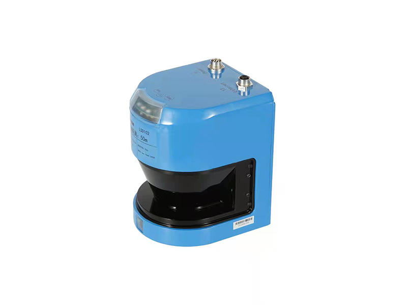
Aluminum alloy casting shell, strong structure and light weight, easy for installation;
Grade 1 laser is safe to people eyes;
50Hz scanning frequency satisfy the high-speed detection demand;
Internal integrated heater ensures the normal operation in low temperature;
Self-diagnosis function ensures the normal operation of the laser radar;
The longest detection range is up to 50 meters;
The detection angle:190°;
Dust filtering and anti-light interference, IP68, fit for outdoor use;
Switching input function(LSD121A,LSD151A)
Be independent of external light source and can keep good detection state at night;
CE certificate
Product Detail
System components
The basis system of LSD1XXA is consisted of one LSD1XXA laser radar, one power cable(Y1), one communication cable(Y3) and one PC with debugging software 。
1.2.1 LSD1XXA
| No | Components | Instruction |
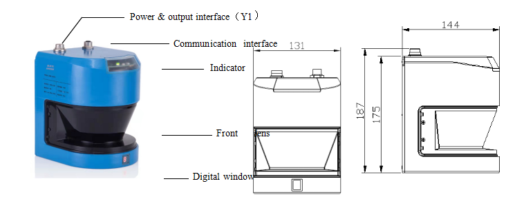
| 1 | Logic interface(Y1) | Power and I/O input cables are connected with radar by this interface |
| 2 | Ethernet interface(Y3) | Ethernet communication cable are connected with radar by this interface |
| 3 | Indicator window | System operation, Fault alarm and system output three indicators |
| 4 | Front lens cover | Emitting and receiving light beams realize the scanning of objects by this lens cover |
| 5 | Digital indication window | The status of Nixie tube is shown at this window |
Power cable
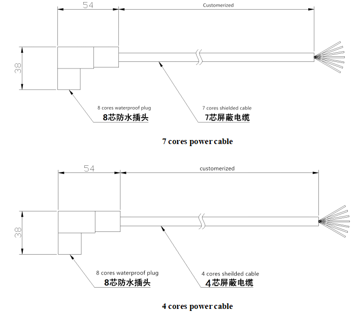
Cable definition
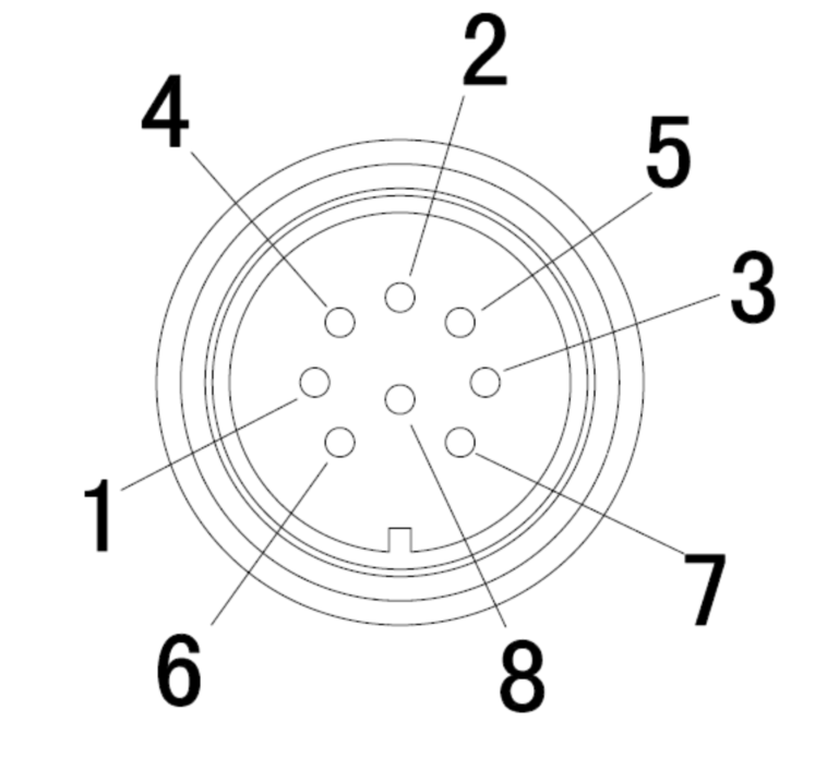
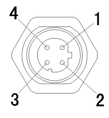
7-cores power cable:
|
Pin |
Terminal No |
Color |
definition |
Function |
 |
1 |
Blue |
24V- |
Negative input of power supply |
|
2 |
Black |
HEAT- |
Negative input of heating power |
|
|
3 |
White |
IN2/OUT1 |
I/O input / NPN output port 1(same to OUT1) |
|
|
4 |
Brown |
24V+ |
Positive input of power supply | |
|
5 |
Red |
HEAT+ |
Positive input of heating power |
|
|
6 |
Green |
NC/OUT3 |
I/O input / NPN output port 3(same to OUT1) |
|
|
7 |
Yellow |
INI/OUT2 |
I/O input / NPN output port2(same to OUT1) |
|
|
8 |
NC |
NC |
- |
Note:For LSD101A、LSD131A、LSD151A, this port is NPN output port(open collector),there will be low lever output when object is detected at the detection area.
For LSD121A, LSD151A, this port is I/O input port, When the input is suspended or connected to low, it is identified as high level and output as "0" in the communication protocol.
4-cores power cable:
|
Pin |
Terminal No |
Color |
definition |
Function |
|
|
1 |
Blue |
24V- |
Negative input of power supply |
| 2 |
White |
HEAT - |
Negative input of heating power |
|
| 3 |
NC |
NC |
Blank | |
| 4 |
Brown |
24V+ |
Positive input of power supply | |
| 5 |
Yellow |
HEAT+ |
Positive input of heating power |
|
| 6 |
NC |
NC |
Blank |
|
| 7 |
NC |
NC |
Blank |
|
| 8 |
NC |
NC |
Blank |
Communication Cable
1.3.3.1 Communication cable
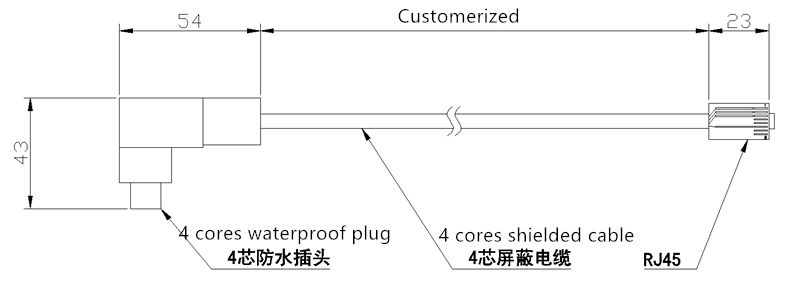
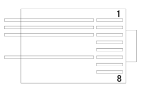
1.3.3.2 Cable definition
|
Pin |
No |
Color |
Definition |
Function |
No |
RJ45 |
|
1 |
Orange white | TX+E |
Ethernet data sending |
1 |
 |
|
|
2 |
Green white | RX+E |
Ethernet data receiving |
3 |
||
|
3 |
Orange |
TX-E |
Ethernet data sending |
2 |
||
|
4 |
Green |
RX-E |
Ethernet data receiving |
6 |
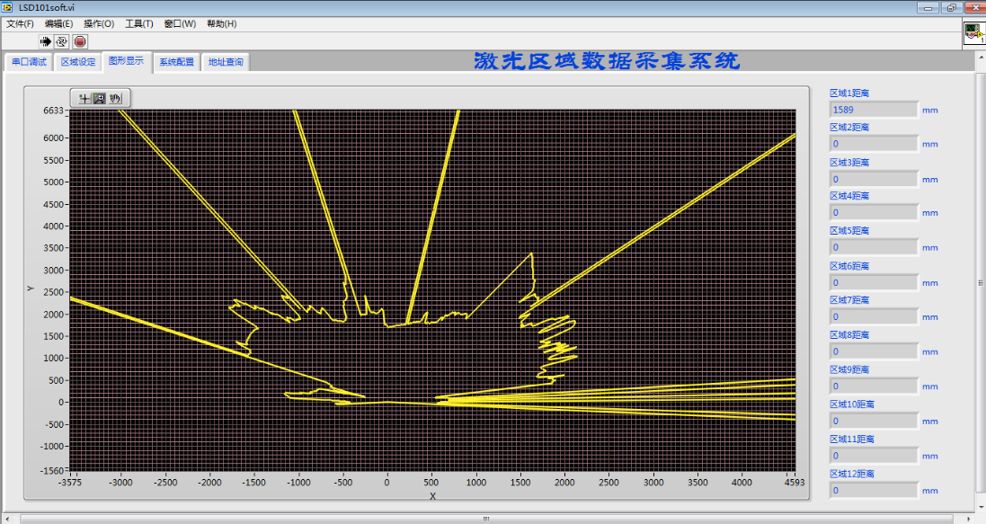
PC
The following figure is an example of PC test. For the specific operation o please refer to "LSD1xx PC instructions"
Technical parameter
| Model |
LSD101A |
LSD121A |
LSD131A |
LSD105A |
LSD151A |
|
| Supply voltage |
24VDC±20% |
|||||
| Power |
< 60W, Normal working current <1.5A,Heating <2.5A |
|||||
| Data interface口 |
Ethernet,10/100MBd,TCP/IP |
|||||
| Response time |
20ms |
|||||
| Laser wave |
905nm |
|||||
| Laser grade |
Grade 1(safe to people eyes) |
|||||
| Anti-light interference |
50000lux |
|||||
| Angle range |
-5° ~ 185° |
|||||
| Angle resolution |
0.36° |
|||||
| Distance |
0~40m |
0~40m |
0~40m |
0~50m |
0~50m |
|
| Measurement resolution |
5mm |
|||||
| Repeatability |
±10mm |
|||||
| In put function |
– |
I/O 24V |
– |
– |
I/O 24V |
|
| Output function |
NPN 24V |
– |
NPN 24V |
NPN 24V |
– |
|
| Area division function |
● |
– |
– |
● |
– |
|
| Width&height
measurement |
Vehicle detection speed |
– |
– |
≤20km/h |
|
– |
| Vehicle width detection range |
– |
– |
1~4m |
|
– |
|
| Vehicle width detection error |
– |
– |
±0.8%/±20mm |
|
– |
|
| Vehicle height detection range |
– |
– |
1~6m |
|
– |
|
| Vehicle height detection error |
– |
– |
±0.8%/±20mm |
|
– |
|
| Dimension |
|
131mm × 144mm × 187mm |
||||
| Protection rating |
|
IP68 |
||||
| Work/storage temperature |
|
-30℃ ~ +60℃ /-40℃ ~ +85℃ |
||||
Characteristic curve
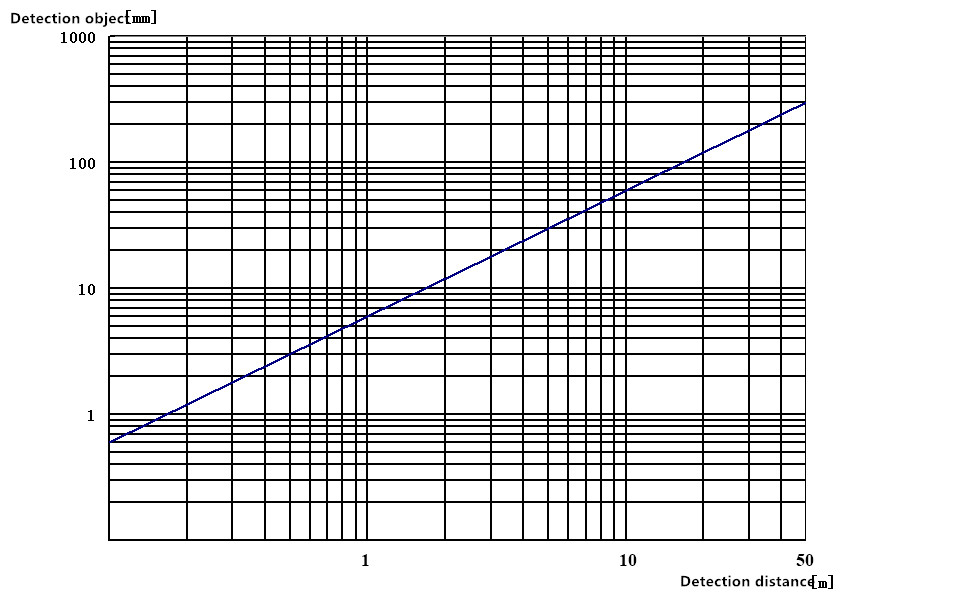
Relationship curve between detection object and distance
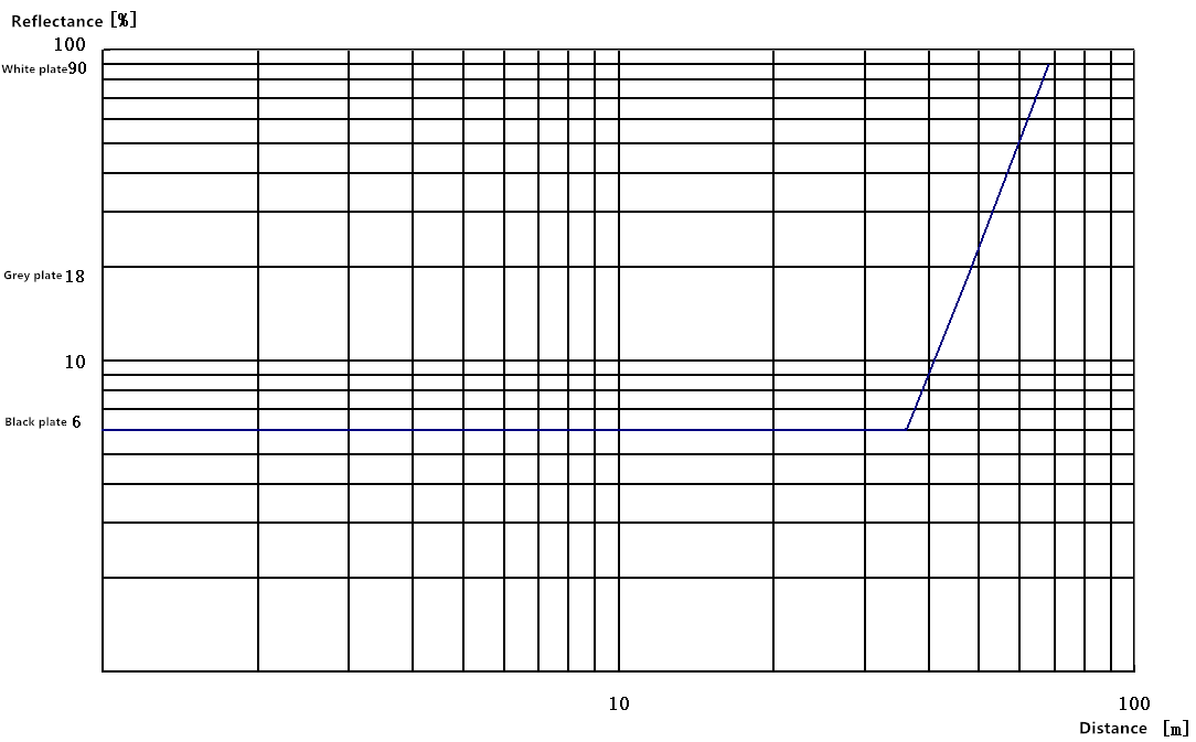
Relationship curve between detection object reflectance and distance
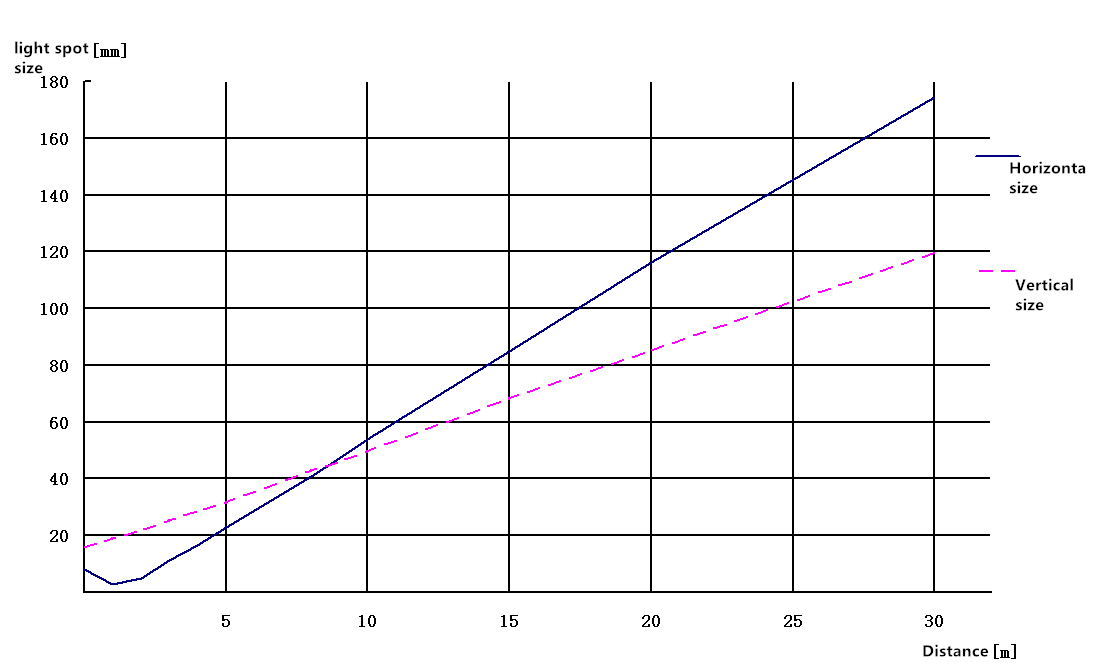
Relationship curve between light spot size and distance
Electrical connection
3.1 Output interface definition
3.1.1 Function description
|
No |
Interface |
type |
Function |
|
1 |
Y1 |
8 pin sockets |
Logical interface:1. Power supply2. I/O input(apply toLSD121A)3. Heating power |
|
2 |
Y3 |
4 pin sockets |
Ethernet interface:1.Measurement data sending2. Reading of sensor port setting, area setting and. fault information |
3.1.2 Interface definition
3.1.2.1 Y1 interface
7-cores interface cable:
|
Pin |
No |
Color |
Signal definition |
Function |
| |
1 |
Blue |
24V- |
Negative input of power supply |
|
2 |
Black |
HEAT- |
Negative input of heating power |
|
|
3 |
White |
IN2/OUT1 |
I/O input / NPN output port 1(same to OUT1) |
|
|
4 |
Brown |
24V+ |
Positive input of power supply | |
|
5 |
Red |
HEAT+ |
Positive input of heating power |
|
|
6 |
Green |
NC/OUT3 |
I/O input / NPN output port 3(same to OUT1) |
|
|
7 |
Yellow |
INI/OUT2 |
I/O input / NPN output port2(same to OUT1) |
|
|
8 |
NC |
NC |
- |
Note :For LSD101A、LSD131A、LSD105A, this port is NPN output port(open collector),there will be low lever output when object is detected at the detection area.
For LSD121A, LSD151A , this port is I/O input port, When the input is suspended or connected to low, it is identified as high level and output as "1" in the communication protocol; When the input is connected to 24V +, it is identified as low level and outputs as "0" in the communication protocol.
4-cores interface cable:
|
Pin |
No |
Color |
Signal definition |
Function |
| |
1 |
Blue |
24V- |
Negative input of power supply |
| 2 |
White |
HEAT - |
Negative input of heating power |
|
| 3 |
NC |
NC |
Blank | |
| 4 |
Brown |
24V+ |
Positive input of power supply | |
| 5 |
Yellow |
HEAT+ |
Positive input of heating power |
|
| 6 |
NC |
NC |
Blank |
|
| 7 |
NC |
NC |
Blank |
|
| 8 |
NC |
NC |
Blank |
3.1.2.2 Y3 interface definition
|
Pin |
No |
Color |
Signal definition |
Function |
 |
1 | Orange white | TX+E |
Ethernet data sending |
| 2 | Green white | RX+E |
Ethernet data receiving |
|
| 3 |
Orange |
TX-E |
Ethernet data sending |
|
| 4 |
Green |
RX-E |
Ethernet data receiving |
3.2 Wiring
3.2.1 LSD101A、LSD131A、LSD105A Switching output wiring(7 cores power cable)
Note:
●When the switch output line is not used, it shall be suspended or grounded, and it shall not be short circuited with the power supply directly;
●V + is not more than 24VDC voltage, and must be grounded together with 24VDC.
3.2.2 LSD121A ,LSD151A Switching output wiring(7 cores power cable)
3.2.3 LSD121A、LSD151A external electronic wiring diagram(7-cores power cable)
The lidar input cable should be connected with external Vout cable meanwhile connect one 5K resistance to 24+
Function and application
4.1 Function
The main functions of LSD1XX A series products are distance measurement, input setting, and comprehensive judgment of vehicle entry and exit process and dynamic separation of vehicles by measuring vehicle width and height information. LSD1XX A series radar is connected to the upper computer through Ethernet cable, and the data graphs and measurement data can be displayed through the upper computer software.
4.2 Measurement
4.2.1 Distance measurement(Apply to LSD101A、LSD121A、LSD105A、LSD151A)
After the radar is powered on and passes the system self-test, it starts to measure the distance value of each point within the range of - 5 ° ~ 185 °, and output these values through the Ethernet interface. The default measurement data is 0-528 groups, corresponding to the distance value in the range of - 5 ° ~ 185 °, which is in hexadecimal format, and the unit is mm. For example:
Fault report
Receive data frame :02 05 00 FE 00 FE 19 FE DB FE 01 02 F9 02 DE 02 E5 02 DE 02 E5 02 E5 02 E5 02 EC 02 EC 02 F3……..
Corresponding distance value:
Date:02 F9 02 DE 02 E5 02 DE 02 E5 02 E5 02 E5 02 EC 02 EC 02 F3。。。
Angle and distance information corresponding to data:-5° 761mm,-4.64° 734mm, -4.28° 741mm , -3.92°734mm , -3.56°741,-3.20° 741mm, -2.84° 741mm,-2.48° 748mm,-2.12° 748mm,1.76° 755mm。。。
4.2.2 Width and height measurement(Apply to LSD131A)
4.2.2.1 Measurement communication protocol
|
Description |
Function code |
Width result |
Height result |
Parity bit |
|
Bytes |
2 |
2 |
2 |
1 |
| Radar sending(Hexadecimal)
|
25、2A |
WH、WL |
HH、HL |
CC |
Illustration:
Width result:WH( high 8 bits)、WL( low 8 bits)
Height result:HH(high 8 bits)、HL(low 8 bits)
Parity bit:CC(XOR check from the second byte to the last second byte)
Example:
Width 2000 Height 1500:25 2A 07 D0 05 DC 24
4.2.2.2 Parameter setting protocol
The factory default settings of the product are: lane width 3500mm, minimum detection object width 300mm, and minimum detection object height 300mm. The user can modify the sensor parameters according to the actual situation. If the sensor is set successfully, a group of status data with the same format will be returned. The specific format of the instruction is as follows
|
Description |
Function code |
Auxiliary function code |
Parameter |
Parity bit |
|
Bytes |
2 |
1 |
6/ 0 |
1 |
|
Radar receiving(Hexadecimal) |
45、4A |
A1(setting) |
DH、DL、KH、KL、GH、GL |
CC |
|
Radar receiving(Hexadecimal) |
45、4A |
AA(query) |
—— |
CC |
| Radar sending(Hexadecimal) |
45、4A |
A1 / A0 |
DH、DL、KH、KL、GH、GL |
CC |
Illustration:
Lane width:DH(high 8 bits)、DL( low 8 bits)
Min detection object width:KH(high 8 bits)、KL(low 8 bits)
Min detection object height:GH(high 8 bits)、GL(low 8 bits)
Parity bit:CC(XOR check from the second byte to the last second byte)
Example:
Setting:45 4A A1 13 88 00 C8 00 C8 70(5000mm,200mm,200mm)
Query:45 4A AA E0
Response 1:45 4A A1 13 88 00 C8 00 C8 70(A1:When the parameter is modified)
Response 2:45 4A A0 13 88 00 C8 00 C8 71(A0:When the parameter is not modified)
Installation
8.1 Installation precautions
● In the outdoor working environment, the lnd1xx should be installed with a protective cover to avoid the internal temperature of the sensor rising rapidly due to direct sunlight。
● Do not install the sensor with over vibrating or swinging objects。
● Lnd1xx shall be installed away from the environment with moisture, dirt and danger of sensor damage。
● In order to avoid external light source such as sunlight, incandescent lamp, fluorescent lamp, strobe lamp or other infrared light source, such external light source shall not be within ± 5 ° of the detection plane。
● When installing the protective cover, adjust the direction of the protective cover and ensure it is in face of the lane, otherwise it will affect the accuracy of measurement
● The rated current of single radar power supply shall be ≥ 3A(24VDC)。
● The same kind of light source interference shall be avoided. When multiple sensors are installed at the same time, the following installation methods shall be followed
a. Install isolation plate between adjacent sensors。
b. Adjust the installation height of each sensor so that the detection plane of each sensor is not within ± 5 degrees of each other's detection plane。
c. Adjust the installation angle of each sensor so that the detection plane of each sensor is not within ± 5 degrees of each other's detection plane。
Trouble codes and troubleshooting
Trouble codes
|
No |
Trouble |
Description |
|
001 |
Parameter configuration fault |
Configuration of machine working parameters through upper computer is incorrect |
|
002 |
Front lens cover fault |
The cover is polluted or damaged |
|
003 |
Measurement reference fault |
The measurement data of bright and dark reflectors inside the machine is incorrect |
|
004 |
Motor fault |
The motor does not reach the set speed, or the speed is unstable |
|
005 |
Communication fault |
Ethernet communication, measurement data transmission blocked or disconnected |
|
006 |
Output fault |
Output short circuit or off |
9.2 Troubleshooting
9.2.1 Parameter configuration fault
Reconfigure the working parameters of the radar through the upper computer and transmit them to the machine。
9.2.2 Front lens cover fault
The front mirror cover is an important part of LSD1xxA. If the front mirror cover is polluted, the measurement light will be affected, and the measurement error will be large if it is serious. Therefore, the front mirror cover must be kept clean. When the front mirror cover is found dirty, please use a soft cloth dipped with neutral detergent to wipe in the same direction. When there are particles on the front mirror cover, blow them off with gas first, and then wipe them to avoid scratching the mirror cover.
9.2.3 Measurement reference fault
The measurement reference is to verify whether the measurement data is valid. If there is a fault, it means that the measurement data of the machine is not accurate and cannot be used any more. It needs to be returned to the factory for maintenance.
9.2.4 Motor fault
Failure of the motor will cause the machine to fail to scan for measurement or result in inaccurate response time. Need to return to factory for maintenance。
9.2.5 Communication fault
Check the communication cable or machine failure
9.2.6 Output fault
Check the wiring or machine failure
Appendix II ordering information
|
No |
Name |
Model |
Note |
Weight(kg) |
|
1 |
Radar Sensor |
LSD101A |
Common type |
2.5 |
|
2 |
|
LSD121A |
In-put type |
2.5 |
|
3 |
|
LSD131A |
Width & height measurement type |
2.5 |
|
4 |
|
LSD105A |
Long distance type |
2.5 |
|
5 |
|
LSD151A |
In-put type Long distance type |
2.5 |
|
6 |
Power cable |
KSP01/02-02 |
2m |
0.2 |
|
7 |
|
KSP01/02-05 |
5m |
0.5 |
|
8 |
|
KSP01/02-10 |
10m |
1.0 |
|
9 |
|
KSP01/02-15 |
15m |
1.5 |
|
10 |
|
KSP01/02-20 |
20m |
2.0 |
|
11 |
|
KSP01/02-30 |
30m |
3.0 |
|
12 |
|
KSP01/02-40 |
40m |
4.0 |
|
13 |
Communication cable |
KSI01-02 |
2m |
0.2 |
|
14 |
|
KSI01-05 |
5m |
0.3 |
|
15 |
|
KSI01-10 |
10m |
0.5 |
|
16 |
|
KSI01-15 |
15m |
0.7 |
|
17 |
|
KSI01-20 |
20m |
0.9 |
|
18 |
|
KSI01-30 |
30m |
1.1 |
|
19 |
|
KSI01-40 |
40m |
1.3 |
|
20 |
Protective cover |
HLS01 |
|
6.0 |
Enviko has been specializing in Weigh-in-Motion Systems for over 10 years. Our WIM sensors and other products are widely recognized in the ITS industry.