
Piezoelectric Traffic Sensor for AVC (Automatic Vehicle Classification)

Short Description:
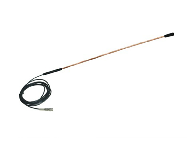
The CET8311 intelligent traffic sensor is designed for permanent or temporary installation on the road or under the road to collect traffic data. The unique structure of the sensor allows it to be mounted directly under the road in a flexible form and thus conforms to the contour of the road. The flat structure of the sensor is resistant to road noise caused by bending of the road surface, adjacent lanes, and bending waves approaching the vehicle. The small incision on the pavement reduces damage to the road surface, increases installation speed, and reduces the amount of grout required for installation.
Product Detail
Introduction
The CET8311 intelligent traffic sensor is designed for permanent or temporary installation on the road or under the road to collect traffic data. The unique structure of the sensor allows it to be mounted directly under the road in a flexible form and thus conforms to the contour of the road. The flat structure of the sensor is resistant to road noise caused by bending of the road surface, adjacent lanes, and bending waves approaching the vehicle. The small incision on the pavement reduces damage to the road surface, increases installation speed, and reduces the amount of grout required for installation.
The advantage of CET8311 intelligent traffic sensor is that it can obtain accurate and specific data, such as accurate speed signal, trigger signal and classification information. It can feedback traffic information statistics for a long time, with good performance, high reliability and easy installation. High cost performance, mainly used in the detection of axle number, wheelbase, vehicle speed monitoring, vehicle classification, dynamic weighing and other traffic areas.
Overall dimension
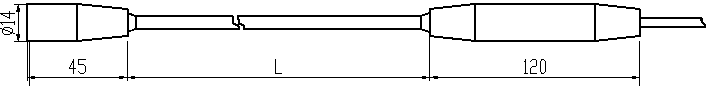
Ex: L=1.78 meters; Sensor’s length is 1.82 meters; Overall length is 1.94 meters
|
Sensor Length |
Visible Brass Length |
Overall Length(including ends) |
|
6'(1.82m) |
70''(1.78m) |
76''(1.93m) |
|
8'(2.42m) |
94''(2.38m) |
100''(2.54m) |
|
9'(2.73m) |
106''(2.69m) |
112''(2.85m) |
|
10'(3.03m) |
118''(3.00m) |
124''(3.15m) |
|
11'(3.33m) |
130''(3.30m) |
136''(3.45m) |
Technical parameters
|
Model No. |
QSY8311 |
|
Section size |
~3×7mm2 |
|
Length |
can be customized |
|
Piezoelectric coefficient |
≥20pC/N Nominal value |
|
Insulation resistance |
>500MΩ |
|
Equivalent capacitance |
~6.5nF |
|
Working temperature |
-25℃~60℃ |
|
Interface |
Q9 |
| Mounting bracket | Attach the mounting bracket with the sensor (Nylon material not recycled). 1 pcs bracket each 15 cm |
Installation preparation
Choice of road section:
a)Requirement on weighing equipment: Long time stability and reliability
b)Requirement on roadbed: Rigidness
Method of installation
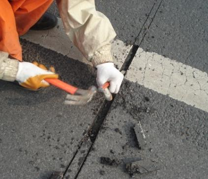
5.1 Cutting slot:
|
Steps |
Picture |
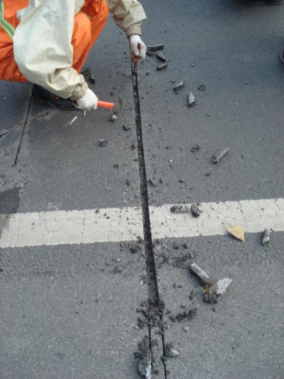
| 1) Construction warning signs should be placed in front of the construction site.2)Draw line: use tape, slate pencil and ink fountain to draw and mark the position where the sensor is placed, also ensure that the cables are long enough to connect to roadside cabinet.3) Cutting slot: use a cutter to open a square groove on the road along the marking line. The cross-sectional dimension of the groove should be accurately controlled within the specified range (see diagram at right side). According to the length of the sensor, deepen the depth of the groove ends to 50mm (to adapt to the sensor output head and end).
4)Road breaking: use a hammer to groove and trim the bottom of the groove. The bottom of the groove should be trimmed as smoothly as possible. According to the drawing: the right picture and the relevant basic construction drawings. Main equipment: pavement cutting machine, impact hammer, hoe, drill. Note: Control the crushing depth of the mounting groove. If it is too shallow, the sensor and the bracket cannot be seated. If it is too deep, the amount of grout will be large. grout will be large. |
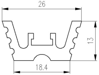
1) Cross Section dimension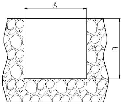
A=20mm(±3mm)mm; B=30(±3mm)mm 2) Groove’s length The length of the slot should be more than 100 to 200 mm of the total length of the sensor. Total length of sensor: i=L+165mm, L is for brass length (See the label). |
5.2 Clean and dry steps
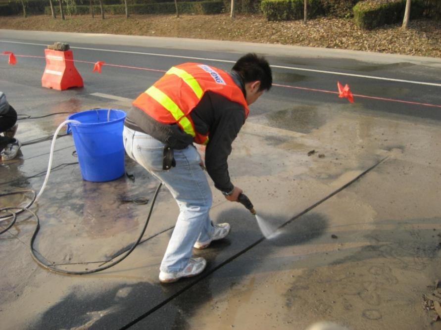
1, In order to ensure that the potting material can be well combined with the road surface after filling, the installation slot should be washed with a high-pressure cleaner, and the surface of the groove should be washed with a steel brush, and the air compressor/ high pressure air gun or blower is used after cleaning to dry the water.
2, After the debris has been cleaned, the floating ash on the construction surface should be cleaned too. If there is accumulated water or obvious visible moisture, use an air compressor (high pressure air gun) or blower to dry it.
3, After the cleaning is completed, sealing tape (width greater than 50mm) is applied
to the road surface around the notch to prevent contamination to the grout.
5.3Pre-installation test
1, Test capacitance: Use a digital multi-meter to measure the total capacitance of the sensor with the cable attached. The measured value should be within the range specified by the corresponding length sensor and cable data sheet. The range of the tester is usually set to 20nF. The red probe is connected to the core of the cable, and the black probe is connected to the outer shield. Note that you should not hold both connection ends at the same time.
2, Test resistance: Measure the resistance at both ends of the sensor with a digital multi-meter. The meter should be set to 20MΩ. At this time, the reading on the watch should exceed 20MΩ, usually indicated by “1”.
5.4 Fix mounting bracket
|
Steps |
Picture |
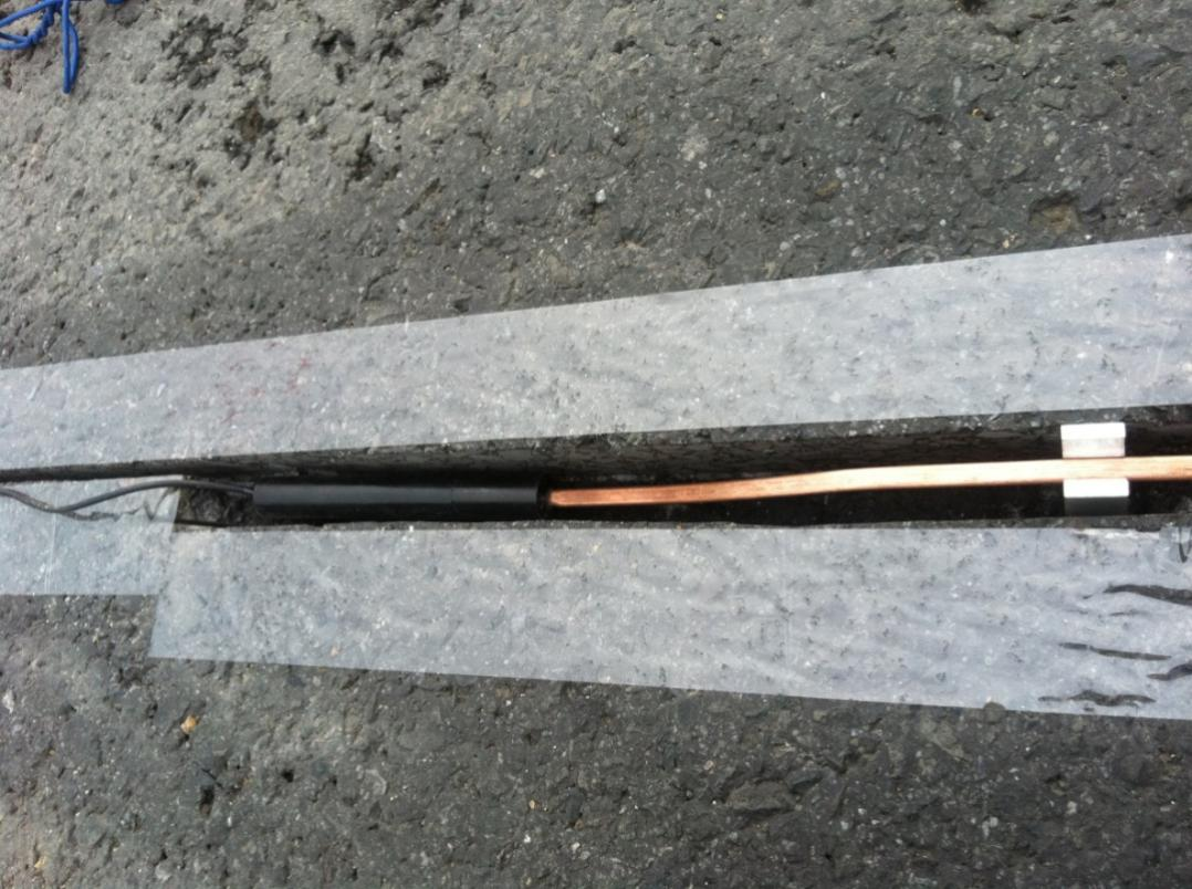
| 1) Unpack the sensor and check if the sensor is intact. Straighten the sensor to keep the sensor straight and flat.2) Open the mounting bracket in the box and install the bracket along the sensor about 15cm intervals.3) Put the mounting bracket together with the sensor
into the cutting slot. The upper surface of all the brackets is about 10mm away from the road surface. 4)Bend the sensor end down 40°, bend the joint down 20°, then bend it 20° upward to level. |
 Dimension Dimension
|
5.5Mix grout
Note: Please read the instructions of the grout carefully before mixing.
1)Open the potting grout, according to the filling speed and the required dosage, it can be carried out in small quantities but a few times to avoid waste.
2)Prepare a proper amount of potting grout according to the specified ratio, and stir evenly with electric hammer stirrer (about 2 minutes).
3)After preparation, please use up within 30 minutes to avoid solidification in the bucket.
5.6First grout filling steps
1)Pour the grout evenly along the length of the groove.
2)When filling, the drainage port can be formed manually to facilitate the control of speed and direction during pouring. In order to save time and physical strength, it can be poured with smaller capacity containers, which is convenient for multiple people to work at the same time.
3)The first filling should be full filled slots, and make grout surface slightly higher than pavement.
4)Save time as much as possible, otherwise the grout will solidify (this product has a normal curing time of 1 to 2 hours).
5.7Second grout filling steps
After the first grouting is basically cured, observe the surface of the grout. If the surface is lower than the road surface or the surface is dented, remix the grout (see step 5.5) and do the second filling.
The second filling should ensure that the surface of the grout is slightly above the road surface.
5.8Surface grinding
After installation step 5.7 is completed for half hour, and the grout starts to solidify, tore off tapes on sides of the slots.
After installation step 5.7 is completed for 1 hour, and grout solidified completely, grind the
grout with an angle grinder to make it flush with the road surface.
5.9On-site cleaning and post-installation testing
1)Clean up grout residue and other debris.
2)Testing after installation:
(1)Test capacitance: use a digital multiple meter to measure the total capacitance of the sensor with the cable attached. The measured value should be within the range specified by the corresponding length sensor and cable data sheet. The range of the tester is usually set to 20nF. The red probe is connected to the core of the cable, and the black probe is connected to the outer shield. Be careful not to hold the two connection ends at the same time.
(2)Test resistance: use a digital multiple meter to measure the resistance of the sensor. The meter should be set to 20MΩ. At this time, the reading on the watch should exceed 20MΩ, usually indicated by “1”.
(3)Pre-load test: after the installation surface is cleaned, connect the sensor output to the oscilloscope. The typical setting of the oscilloscope is: Voltage 200mV/div, Time 50ms/div. For the positive signal, the trigger voltage is set to about 50mV. A typical waveform of a truck and a car is collected as a pre-load test waveform, and then the test waveform is stored and copied out for printing, and permanently saved. The output of the sensor depends on the mounting method, the length of the sensor, the length of the cable and the potting material used. If the preload test is normal, the installation is complete.
3) Traffic release: remarks: Traffic can only be released when the potting material is fully cured (about 2-3 hours after the last filling). If the traffic is released when the potting material is incompletely cured, it will damage the installation and cause the sensor to fail prematurely.
Preload test waveform
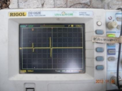
2 Axes
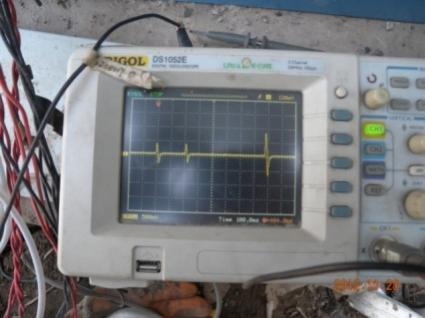
3 Axes
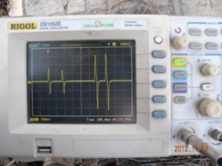
4 Axes
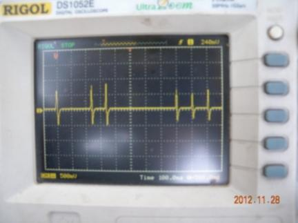
6 Axes
Enviko has been specializing in Weigh-in-Motion Systems for over 10 years. Our WIM sensors and other products are widely recognized in the ITS industry.


