Piezoelectric Quartz Dynamic Weighing Sensor CET8312

Short Description:
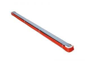
CET8312 Piezoelectric Quartz Dynamic Weighing Sensor has the characteristics of wide measuring range, good long-term stability, good repeatability, high measurement precision and high response frequency, so it is especially suitable for dynamic weighing detection. It is a rigid, strip dynamic weighing sensor based on piezoelectric principle and patented structure. It is composed of piezoelectric quartz crystal sheet, electrode plate and special beam bearing device. Divided into 1-meter, 1.5-meter, 1.75-meter, 2-meter size specifications, can be combined into a variety of dimensions of road traffic sensors, can adapt to the dynamic weighing needs of the road surface.
Product Detail
Technical Parameters
| Cross section dimensions | (48mm+58mm)*58 mm | ||
| Length |
1m, 1.5m, 1.75m, 2m |
||
| Wheel weighing range | 0.05T~40T | ||
| Overload capacity | 150%FS | ||
| Load sensitivity | 2±5%pC/N | ||
| Speed range |
(0.5-200)km/h |
||
| Protection grade |
IP68 |
Output impedance |
>1010Ω |
| Working temp. |
-45~80℃ |
Output temperature effect |
<0.04%FS/ ℃ |
| Electrical connection | High frequency static noise coaxial cable | ||
| Bearing surface | Bearing surface can be polished | ||
| Nonlinear | ≤±2% FS (precision of static calibration of sensors at each point) | ||
| Consistency | ≤±4% FS (static calibration accuracy of different position points of the sensor) | ||
| Repetitiveness | ≤±2% FS (precision of static calibration of sensors at the same position) | ||
| Integrated precision error |
≤±5% |
||
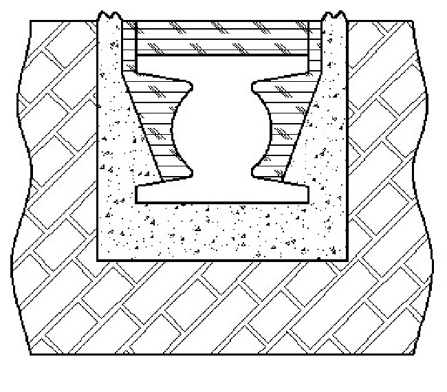
Installation Method
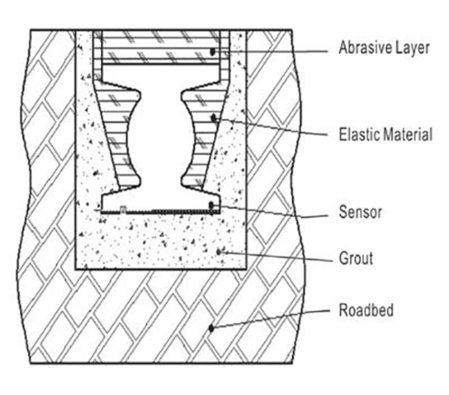
Overall Structure
In order to ensure the testing effect of the whole installation of the sensor, the site selection should be strict. It is suggested that the rigid cement pavement should be chosen as the sensor installation basis, and the flexible pavement such as asphalt should be reformed. Otherwise, the accuracy of measurement or the service life of the sensor may be affected.
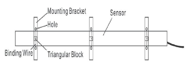
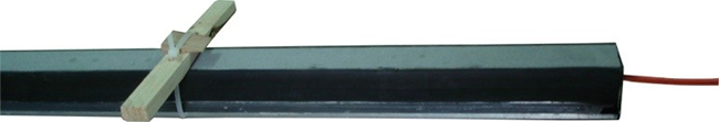
Mounting Bracket
After the location is determined, the mounting bracket with holes provided with the sensors should be fixed to the sensor with a longer tie-wire tape, and then a small triangle piece of wood is used to plug into the gap between the tie-up belt and the mounting bracket, so that it can be tightened. If the manpower is sufficient, step (2) and (3) can be carried out simultaneously. As shown above.
Pavement Grooving
Use a ruler or other tool to determine the mounting position of the dynamic weighing sensor. The cutting machine is used to open rectangular grooves on the road.
If the grooves are uneven and have small bumps on the edge of the grooves, the width of the grooves is 20 mm more than that of the sensor, the depth of the grooves is 20 mm more than that of the sensor, and 50 mm longer than that of the sensor. Cable groove is 10 mm wide, 50 mm deep;
If the grooves are meticulously made and the edges of the grooves are smooth, the width of the grooves is 5-10mm more than that of the sensors, the depth of the grooves is 5-10mm more than that of the sensors, and the length of the grooves is 20-50mm more than the sensors. Cable groove is 10 mm wide, 50 mm deep.
The bottom shall be trimmed, the silt and water in the grooves shall be blown clean with the air pump (to be thoroughly dried to fill the grout), and the upper surface of both sides of the grooves shall be attached with tape.
First Time Grouting
Open the installation grout, according to the prescribed proportion to prepare the mixed grout, quickly mixing the grout with tools, and then evenly pour along the groove length direction, the first filling in the groove should be less than 1/3 of the depth of the groove.
Sensor Placement
Gently place the sensor with the mounting bracket into the grout-filled slot, adjust the mounting bracket and make each fulcrum touch the upper surface of the slot, and ensure that the sensor is in the center of the slot. When two or more sensors are installed in the same slot, special attention should be paid to the connection part.
The upper surface of the two sensors must be in the same horizontal level, and the joint shall be as small as possible, otherwise the measurement error will be caused. Save as much time as possible at step (4) and (5), or the grout will cure (1-2 hours of normal curing time of our glue).
Removal of Mounting Bracket and Second Grouting
After the grout is basically cured, observe the initial installation effect of the sensor, and adjust it timely if necessary. Everything is basically ready, then remove the bracket, carry on second grouting. This injection is limited to the surface height of the sensor.
Third Time Grouting
During the curing period, pay attention to increasing the amount of grout at any time, so that the overall level of grout after filling is slightly higher than the road surface.

Surface Grinding
After all the installation grout have reached the curing strength, tear off the tape, and grind the groove surface and the road surface, conduct preloading test with the standard vehicle or other vehicles to check whether the sensor installation is ok.
If the preloading test is normal, the installation is
completed.
Installation Notices
5.1It is strictly prohibited to use the sensor beyond range and operating temperature for a long time.
5.2It is strictly prohibited to measure the insulation resistance of the sensor with a high resistance meter above 1000V.
5.3Non-professional personnel are strictly prohibited to verify it.
5.4The measuring medium should be compatible with aluminum materials, otherwise special instructions are required when ordering.
5.5The output end of sensor L5/Q9 should be kept dry and clean during measurement, otherwise the signal output is unstable.
5.6The pressure surface of the sensor shall not be struck with a blunt instrument or heavy force.
5.7The bandwidth of the charge amplifier shall be higher than that of the sensor, except there is no special requirement for frequency response.
5.8The installation of sensors should be carried out in strict accordance with the relevant requirements of the instructions in order to achieve accurate measurement.
5.9If there is strong electromagnetic interference near the measurement, certain shielding measures should be taken.
5.10The cable of the sensor and the charge amplifier must use a coaxial cable with high frequency static noise.
Attachments
Manual 1 PCS
Qualification of verification 1 PCS Certificate 1 PCS
Hangtag 1 PCS
Q9 output cable 1 PCS
Enviko has been specializing in Weigh-in-Motion Systems for over 10 years. Our WIM sensors and other products are widely recognized in the ITS industry.