
First, the system composition
1.The highway overload non-stop detection system is generally composed of the front-end freight vehicle overload information collection and forensics system and the back-end freight vehicle overload information management.
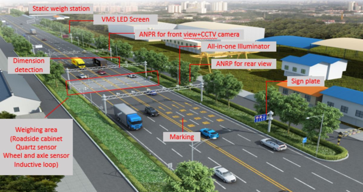
2. The front-end freight vehicle overload information collection and forensics system is generally composed of non-stop weighing equipment, vehicle profile size detection equipment, license plate recognition and capture equipment, vehicle detector, video surveillance equipment, information release equipment, traffic signs, power supply and lightning protection facilities, on-site control cabinets, information collection and processing and network transmission equipment, non-stop weighing and detection area, traffic sign marking and related supporting facilities.
3. The back-end freight vehicle overload information management (including direct enforcement) platform is generally composed of county (district), municipal and provincial overload information management (including direct enforcement) platforms.
2. Functional requirements
1. Functional requirements for non-stop weighing equipment
1.1 Operating speed range
The speed range of the non-stop weighing equipment is (0.5~100) km/h for freight vehicles to pass through the non-stop detection area.
1.2 Accuracy level of total vehicle weight
(1) The maximum allowable error of the weighing of the total weight of the vehicle and cargo within the allowable operating speed range of the non-stop weighing equipment shall not be lower than the provisions and requirements of the accuracy level 5 and 10 in the JJG 907 "Dynamic Highway Vehicle Automatic Weighing Apparatus Verification Regulations" (Table 2-1).
Table 2-1 Maximum allowable error of dynamic weighing of total vehicle weight
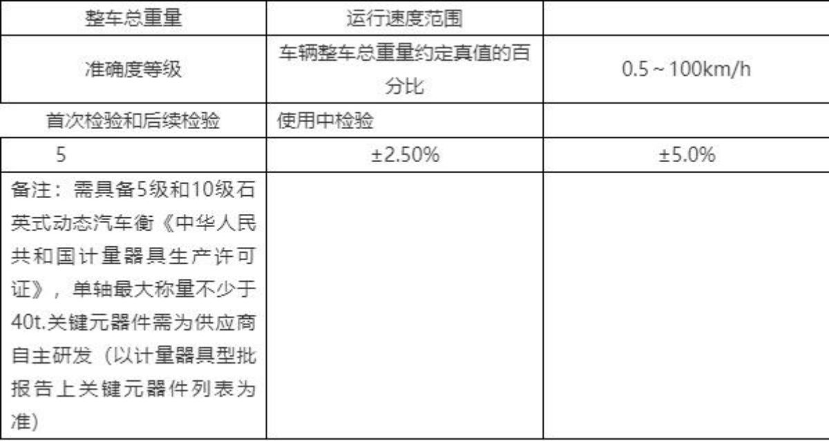
(2) When the freight vehicle passes through the non-stop weighing detection area with abnormal driving behaviors such as frequent acceleration and deceleration, jumping scale, stopping, S bend, crossing, pressure line, reverse driving or stop-and-go in a short period of time, the accuracy level of the total weight of the vehicle of the non-stop weighing equipment shall not be lower than the provisions and requirements of Table 2-1. (Pressing lanes and driving in the opposite direction are important).
1.3 The load cell used in the non-stop weighing equipment shall comply with the provisions and requirements of GB/T7551 "Load Cell", the service life shall be ≥ 50 million axles, and the protection level of the load cell used in non-stop weighing shall not be less than IP68. 。
1.4 The average trouble-free working time of non-stop weighing equipment shall not be less than 4000h, and the warranty period of key components shall not be less than 2 years, and the service life shall not be less than 5 years.
1.5 Power-off protection requirements
(1) When the power is off, the non-stop weighing equipment should be able to automatically store the currently set parameters and weighing information, and the storage time should not be less than 72h.
(2) In the case of power failure, the internal clock running time of the non-stop weighing equipment should not be less than 72d.
1.6 Anti-corrosion treatment requirements
The exposed metal parts of non-stop weighing equipment should be treated with anti-corrosion treatment in accordance with the relevant provisions of GB/T18226 "Technical Conditions for Anti-corrosion of Steel Components in Highway Traffic Engineering".
1.7 The speed measurement error of the vehicle detector of the non-stop weighing equipment should be ≤± 1km/h, and the accuracy of the traffic flow detection should be ≥99%.
1.8 The technical requirements for vehicle separators for non-stop weighing equipment are as follows:
(1) The detection accuracy of the number of axes should be ≥98%.
(2) The detection error of shaft spacing should be ≤± 10cm.
(3) The accuracy of vehicle classification should be ≥ 95%.
(4) The cross-channel recognition rate should be ≥98%.
1.9 The applicable range of working environment temperature should meet -20°C~+80°C, and the technical indicators of environmental humidity resistance should meet the relevant regulations and requirements of outdoor mechanical and electrical equipment of JT/T817 "General Technical Requirements and Testing Methods for Highway Electromechanical System Equipment".
1.10 Rainproof and dustproof measures should be taken, and the protection level should meet the provisions and requirements of JT/T817.
2. Functional requirements for vehicle profile size testing equipment
2.1 When the freight vehicle passes through the non-stop weighing detection area at a speed of (0.5~100) km/h, it should be able to automatically complete the real-time rapid detection of the geometric dimensions and 3D model of the length, width and height of the freight vehicle, and output the correct identification results. The response time should not be less than 30ms, and the time to complete a single detection and output result should not be more than 5s.
2.2 The geometric measurement range of the length, width and height of the freight vehicle shall meet the requirements of Table 2-2.
Table 2-2 Measurement range of vehicle profile size testing equipment
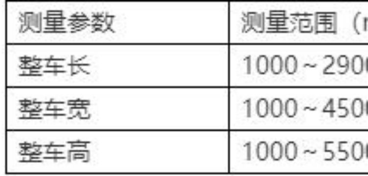
2.3 The geometric dimension measurement resolution of the length, width and height of the freight vehicle is not more than 1mm, and the measurement error of the vehicle outline size detection equipment should meet the following requirements within the range of 1~100km/normal operating speed: (in terms of running speed, it should be consistent with the requirements of the previous dynamic weighing equipment).
(1) Length error≤±500mm;
(2) Width error≤±100mm;
(3) The height error ≤± 50mm.
2.4 The frequency of laser spot detection of vehicle profile size testing equipment should be ≥1kHz, and it should have 9 types of vehicle models and vehicle speed detection functions specified in the motor vehicle GB1589 "Outline Size, Axle Load and Quality Limits of Automobiles, Trailers and Automobile Trains".
2.5 It should have the functions of parallel freight vehicles, S-bend driving state judgment, black material shielding and high reflectivity material cargo vehicle profile geometric size detection.
2.6 should have the classification of freight motor vehicle models, traffic volume, location speed, front time distance, following the car percentage, front spacing, time occupancy detection functions. And the classification accuracy of freight motor vehicle models should be ≥ 95%.
2.7 The applicable range of working environment temperature should meet -20 °C ~ +55 °C, and the technical indicators of environmental humidity resistance should meet the relevant regulations and requirements of outdoor mechanical and electrical equipment of JT/T817 "General Technical Requirements and Testing Methods for Highway Electromechanical System Equipment".
2.8 Laser vehicle profile size testing equipment should be installed with a gantry with a maintenance channel
2.9 The protection level of the vehicle profile size testing equipment shall not be less than IP67.
3. Functional requirements for license plate recognition and capture equipment
3.1 The functional requirements of license plate recognition and capture equipment shall meet the relevant provisions and requirements of GB/T 28649 "Automatic Identification System for Motor Vehicle Number Plates".
3.2 The license plate recognition and capture equipment shall be equipped with a fill light or flashing light, which shall be able to clearly capture the vehicle number passing through the non-stop weighing detection area under any weather conditions, and output the correct identification result.
3.3 The license plate recognition and capture equipment should ≥ 99% of the license plate recognition accuracy during the day, and the ≥95% accuracy of the license plate recognition at night, and the recognition time should not be more than 300ms.
3.4 The image of the collected freight vehicle number plate should be clearly output in full-width JPG format, and the recognition result should include the recognition time, license plate color, etc.
3.5 license plate recognition capture image pixels should not be less than 5 million, other capture image pixels should not be less than 3 million, freight vehicles through the non-stop weighing detection area, should capture the front of the vehicle, two sides of the vehicle and the rear of the vehicle a total of not less than 4 high-definition images.
3.6 According to the front high-definition image information, the freight vehicle license plate area, the front and cab characteristics, the front color, etc., should be able to clearly distinguish the number of axles, body color, and the basic situation of the transported goods according to the high-definition image information on the side of the vehicle; according to the high-definition image information of the rear of the vehicle, the tail license plate number, body color and other information can be distinguished.
3.7 Each image should be superimposed with information such as the detection date, testing time, testing location, total weight of the vehicle and cargo, vehicle dimensions, image forensics equipment number, anti-counterfeiting and other information.
3.8 The bandwidth of the captured image information transmission channel shall not be less than 10Mbps.
3.9 It should have fault self-check functions such as abnormal communication and power failure.
3.10 The applicable range of working environment temperature should meet -20 °C ~ +55 °C, and the technical indicators of environmental humidity resistance should meet the relevant regulations and requirements of outdoor mechanical and electrical equipment of JT/T817 "General Technical Requirements and Testing Methods for Highway Electromechanical System Equipment".
3.11 The protection level of license plate recognition and capture equipment shall not be less than IP67.
4 Video Surveillance Equipment Functional Requirements
4.1 video surveillance camera should have infrared day and night camera function, and should be able to non-stop weighing detection area of the all-round camera function, and save not less than 10s of illegal freight vehicle overload evidence collection video data.
4.2 It should have the functions of self-diagnosis, field of view calibration and automatic compensation.
4.3 Forensic video images should be no less than 3 million pixels, and should be clear and stable.
4.4 It should have the function of rotation and zoom, and the horizontal and vertical rotation and lens zoom can be carried out according to the control command.
4.5 It should have the function of cleaning and removing rain and frost fog lamps, and should be able to clean, heat and defrost the protective cover in time.
4.6 Forensic video images should be transmitted to the county (city) level overload information management and direct enforcement platform in real time.
4.7 Video surveillance equipment and other technical indicators of its accessories shall meet the relevant provisions and requirements of GA/T995.
4.8 The applicable range of working environment temperature should meet -20°C~+55°C, and the technical indicators of environmental humidity resistance should meet the relevant regulations and requirements of outdoor mechanical and electrical equipment of JT/T817 "General Technical Requirements and Testing Methods for Highway Electromechanical System Equipment".
5 Functional requirements for information publishing equipment
5.1 It should be able to release real-time information about the overload of the vehicle to the driver of the overload illegal vehicle.
5.2 It should be able to publish and display information such as text alternation and scrolling.
5.3 The main functional indicators and technical indicators of highway LED variable information signs shall meet the relevant provisions and requirements of GB/T23828 "Highway LED Variable Information Signs".
5.4 Double-column gantry type highway LED variable information sign display screen commonly used pixel spacing can be selected: 10mm, 16mm and 25mm. The display area size of four lanes and six lanes can be 10 square meters and 14 square meters respectively. The display content format can be 1 row and 14 columns.
5.5 The pixel spacing of the single-column highway LED variable information sign display can be selected: 10mm, 16mm and 25mm. The size of the display screen can be selected from 6 square meters and 11 square meters. The display content format can be 4 rows and 9 columns.
5.6 The design and setting of highway LED variable information signs and the visual recognition distance should fully consider the actual speed and visual recognition needs of freight vehicles in the road section, and meet the relevant provisions and requirements of GB/T23828 "Highway LED Variable Information Signs".
6 Traffic Sign Setting Requirements
6.1 Set up a traffic sign to enter the "non-stop weighing and detection area" at a distance of not less than 200 meters in front of the non-stop weighing detection area.
6.2 Set up a "no lane change" traffic sign not less than 150 meters in front of the non-stop weighing detection area.
6.3 Set up a traffic sign of "Lift the prohibition of lane change" at a distance of not less than 200 meters behind the non-stop weighing detection area.
6.4 The setting of traffic signs in the non-stop weighing detection area shall comply with the design and requirements of GB5768 "Road Traffic Signs and Markings".
7. Requirements for power supply equipment and lightning protection grounding
7.1 The overload information collection and forensics system shall be equipped with stable and reliable power supply lines, which shall be able to meet the requirements of 24-hour uninterrupted power supply operation.
7.2 Necessary lightning and overvoltage protection measures shall be taken for the power supply interface and control interface of the overload information collection and forensics system and related components, and the protective measures shall comply with the relevant provisions and requirements of JT/T817 "General Technical Requirements and Testing Methods for Highway Electromechanical System Equipment".
7.3 The overload information collection and forensics system should adopt a single-point nearby grounding method, and the DC parallel grounding method should be adopted.
7.4 The lightning protection and electrical resistance of the overload information collection and forensics equipment shall be ≤ 10 Ω, and the protective grounding resistance shall be ≤ 4 Ω.
8 Field control cabinet functional requirements
8.1 The on-site control cabinet configured with the overload information collection and forensics system should be able to store data acquisition processors, vehicle detectors, network switches and other equipment. It should be able to upload the truck overload information to the Provincial Department of Transportation Information Center Traffic Comprehensive Administrative Direct Enforcement Platform, and be able to transmit the truck overload information to the highway LED variable information sign in real time for release and display.
8.2 The control cabinet shall be designed with a double-layer chassis seal, which can effectively prevent dust and rain, and has an independent temperature control system.
8.3 The control cabinet should be designed with slots to facilitate function expansion.
8.4 The control cabinet shall be equipped with data security protection equipment to avoid leakage of over-limit detection data.
9. Requirements for setting up non-stop weighing areas for highway overload
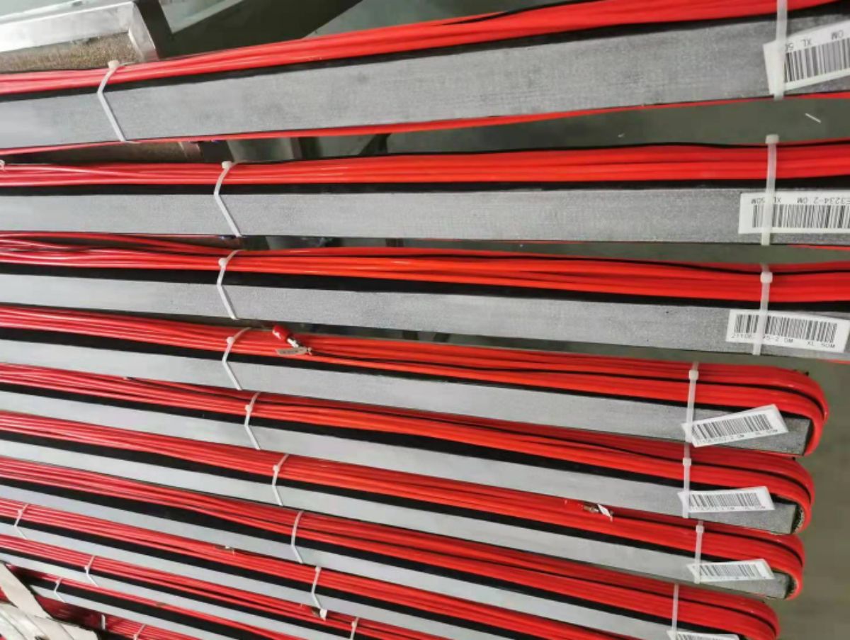
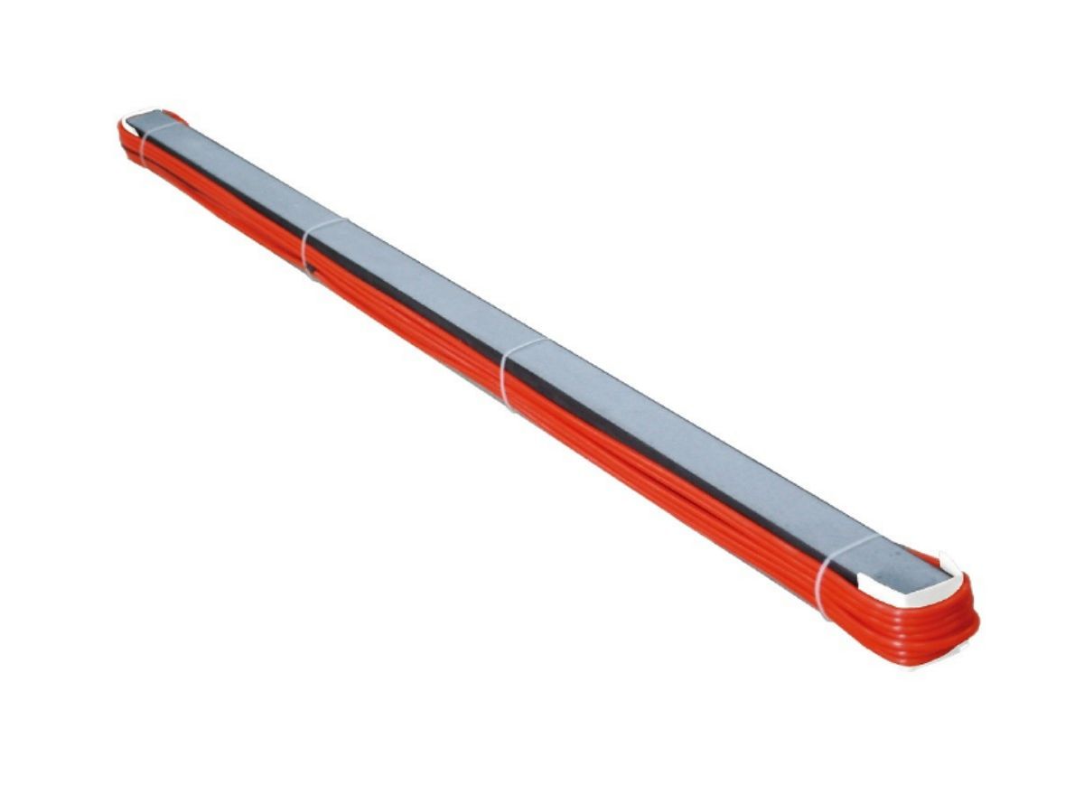
9.1 The non-stop weighing detection area is composed of the non-stop weighing equipment carrier (quartz crystal sensor) and its guide sections at the front and rear ends (according to the hardened road surface of 30 meters in front and 15 meters in the back) (Figure 2-1).
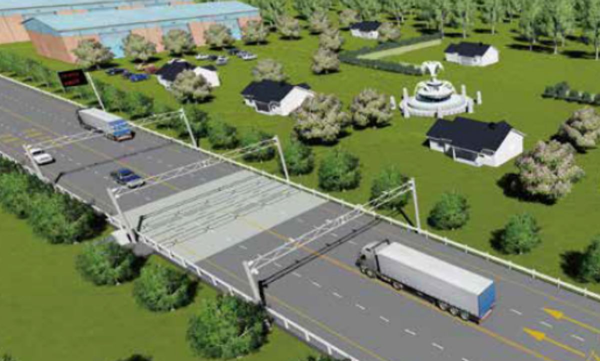
Figure 2-1 Schematic diagram of the non-stop weighing area
9.2 The location of the non-stop weighing and testing area should not be located in flat, the radius of the longitudinal curve is small, the sight distance is poor and the long downhill and other road sections, and the linear indicators should meet the ASTM E1318 "Standard Specification for Highway Weigh-In-Motion (WIM) Systems with User Requirements and Test". Methods, the specific requirements are as follows:
(1) The turning radius of the road centerline of the 60m guide section and the rear 30m guide road section in the non-stop weighing detection area should be ≥ 1.7km.
(2) The longitudinal slope of the road surface in the front 60m guide section and the rear 30m guide road section in the non-stop weighing detection area should be ≤2%.
(3) The pavement transverse slope value i of the front 60m guide road section and the rear 30m guide road section of the non-stop weighing detection area should meet 1% ≤ i ≤2%.
(4) There should be no obstacles blocking the driver's line of sight within the 150m guide road section before the non-stop weighing detection area.
(5) The distance between the location of the non-stop weighing and detection area and the entrance and exit of the highway tunnel on the same road section shall not be less than 2km and shall not be less than 1km.
(6) The horizontal error of the connection between the sensor and the road surface is not higher than 0.1mm
9.3 In order to ensure the accuracy of non-stop weighing data and driving safety, the road lane isolation of the front 60m guide road section and the rear 30m guide road section of the non-stop weighing detection area should be isolated by solid line.
9.4 Non-stop weighing and testing area to guide the construction of road sections
(1) The roadbed of the guide road section should be stable, and the friction coefficient of the pavement should meet the design requirements of the road section.
(2) The pavement surface of the guide road section should be smooth and compact, and the asphalt pavement should not have ruts, potholes, subsidence, congestion, cracks, network cracks, and bulges, and the cement pavement should not have staggered, broken plates, subsidence, mud accumulation and other diseases. The flatness of cement concrete pavement and asphalt concrete pavement shall meet the relevant provisions and requirements of JTGF80-1 "Highway Engineering Quality Inspection and Evaluation Standards".
(3) The width of the road surface of the guide road section should be able to support the normal passage of the widest freight vehicle within the weighing range.
(4) The center line of the pavement in the non-stop weighing and testing area should be isolated by double yellow (single yellow) solid lines, and the lane demarcation line should be isolated by white solid lines.
3. Interface protocol and data format requirements
The interface protocol and data format of the highway overload non-stop detection system should meet the relevant provisions and requirements of the "Fujian Traffic Comprehensive Administrative Direct Enforcement Engineering Design Plan" to ensure interconnection and information sharing between the county (district), municipal and provincial overload information management (including direct enforcement) platforms.

Enviko Technology Co.,Ltd
E-mail: info@enviko-tech.com
https://www.envikotech.com
Chengdu Office: No. 2004, Unit 1, Building 2, No. 158, Tianfu 4th Street, Hi-tech Zone, Chengdu
Hong Kong Office: 8F, Cheung Wang Building, 251 San Wui Street, Hong Kong
Factory: Building 36, Jinjialin Industrial Zone, Mianyang City, Sichuan Province
Post time: Jan-25-2024


