
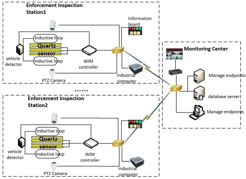
The direct enforcement system consists of weigh-in-motion inspection station and monitoring center, through PL (private line) or internet.
The monitoring site is composed of data acquisition equipment (WIM sensor, ground loop, HD camera, smart ball camera) and data manipulation equipment (WIM controller, vehicle detector, hard disk video, front-end equipment manager) and information display equipment etc. Monitoring center consists of application server, database server, management terminal, HD decoder, display screen hardware and other data platform software. Each monitoring site collects and processes the load, license plate number, image, video and other data of the vehicles passing on the road in real time, and transmits the data to the monitoring center through the optical fiber network.
Weigh-in-motions system working principle
The following is a schematic diagram of how the system works.
Schematic diagram of the working principle of the weigh-in-motion station
1)Dynamic weighing
Dynamic weighing utilizes load cells laid on the road to sense the pressure when the vehicle axle pressure on it. When vehicle drive in the ground loop installed under the road, it is ready to be weighed. When the vehicle tire contacts the load cell, the sensor begins to detect the wheel pressure, generates an electrical signal proportional to the pressure, and after the signal is amplified by the data matching terminal, the axle load information is calculated by the weighing controller. While vehicles left the ground loop, the WIM controller calculate the number of axles, axles weight and vehicle gross weight, and the weighing is completed, sent this vehicle load data to front of manager equipment. While WIM controller can detect both vehicle speed and vehicle type.
2)vehicle image capture/vehicle license plate recognition
Vehicle license plate recognition use HD camera to capture vehicle images for license plate number recognition. When the vehicle enters the ground loop, that
triggers HD camera in the direction of the front and rear of the vehicle to capture the head, back and side of the vehicle, at the same time, with the fuzzy recognition algorithm to get the license plate number, license plate color and vehicle color etc. HD camera can also assist in detecting vehicle type and driving speed.
3)Video acquisition
The integrated ball camera installed on the lane monitoring pole collects the vehicle driving video data in real time and sends it to the monitoring center.
4)Data fusion matching
Data processing and storage subsystem receives from WIM controller subsystem, vehicle license plate recognition/capture subsystem and the vehicle load data, vehicle image data and video data of the video monitoring subsystem matches and binds the vehicle load and image data with the license plate number, and at the same time judge whether the vehicle is overloaded and overrun according to the load standard threshold.
5)overrun & overload reminder
For the overrun and overload vehicles, the license plate number and overload data sent to the variable information board display, reminding and inducing the driver to drive the vehicles away from the main road and accept the treatment.
System Deployment Design
The management department can set vehicle overload and overload monitoring points on roads and bridges according to management needs. The typical equipment deployment mode and connection relationship in one direction of monitoring points are shown in the following figure.
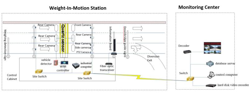
Schematic diagram of typical deployment of the system
The system deployment is divided into two parts: the inspection site and the monitoring center, and the two parts are interconnected through the privateline network or the Internet provided by the operator.
(1)On site detect
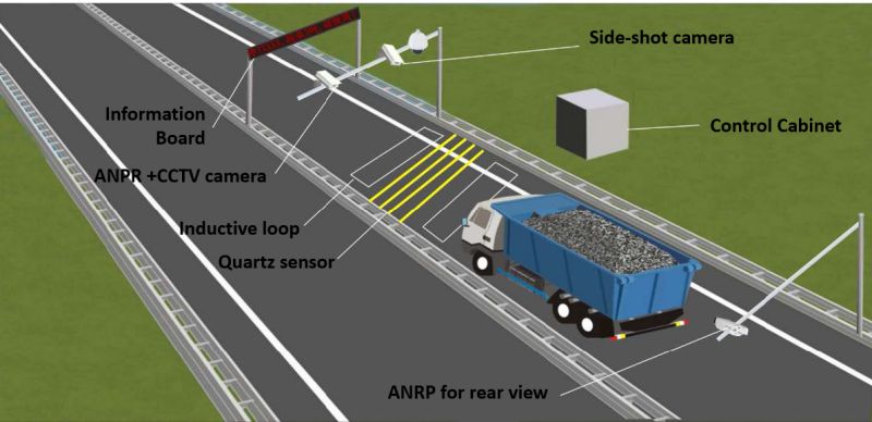
The inspection site is divided into two sets according to the two driving directions, and each set has four rows of quartz pressure sensors and two sets of ground sensing coils respectively laid on the two lanes of the road.
Three F poles and two L poles areerected on the side of the road. Among them, three F bars are installed with weighing inspection prompt boards, information display guidance screens and unloading guide prompt boards, respectively. On the two L bars on the main road are respectively installed with 3 front-end snapshot cameras, 1 side snapshot camera, 1 integrated ball camera, 3 fill lights, and 3 rear snapshot cameras, 3 fill lights.
1 WIM controller, 1industrial computer, 1 vehicle detector, 1 hard disk video recorder, 1 24-port switch, a fiber optic transceiver, power supply and lightning protection grounding equipment are respectively deployed in the roadside control cabinet.
8 high-definition cameras, 1 integrated dome camera, 1 WIM controller, and 1 industrial computer are connected to a 24-port switch through a network cable, and the industrial computer and the vehicle detector are directly connected. The information display guide screen is connected to the 24-port switch through a pair of fiber optic transceivers
(2)Monitoring Center
The monitoring center deploys 1 switch, 1 database server, 1 control computer, 1 high-definition decoder and 1 set of large screens.
Application process design
1)The integrated intelligent ball camera collects the road video information of the inspection point in real time, stores it in the hard disk video recorder, and sends the video stream to the monitoring center in real time for real-time display.
2)When there is a vehicle on the road entering the ground loop in the front row, the ground loop generates an oscillating current, which triggers the license plate recognition/snapshot camera to take pictures of the front, rear and side of the vehicle, and at the same time informs the weighing system to prepare to start weighing;
3)When the vehicle wheel touches the WIM sensor, the quartz pressure sensor starts to work, collects the pressure signal generated by thewheel, and sends it to the weighing instrument for processing after being amplified by the charge;
4)After the weighing instrument performs integral conversion and compensation processing on the pressure electrical signal, the information such as the axle weight, gross weight, and number of axles of the vehicle is obtained, and sent to the industrial computer for comprehensive processing;
5)The license plate recognition/capture camera recognizes the license plate number, license plate color and body color of the vehicle. The results of the identification and the photos of the vehicle are sent to the industrial computer for processing.
6)The industrial computer matches and binds the data detected by the weighing instrument with the vehicle license plate number and other information, and compares and analyzes the vehicle load standard in the database to determine whether the vehicle is overloaded or not.
7)If the vehicle is not overloaded, the above information will be stored in the database and sent to the monitoring center database for storage. At the same time, the vehicle license plate number and load information will be sent to the information guidance LED display for vehicle information display.
8)If the vehicle is overloaded, the road video data within a period of time before and after the weighing will be searched from the hard disk video recorder, bound to the license plate, and sent to the monitoring center database for storage. Go to the information guidance LED display to display the vehicle information, and induce the vehicle to deal with it immediately.
9)Statistical analysis of on-site monitoring data, generating statistical reports, providing user inquiries, and displaying on the large splicing screen, at the same time, the vehicle overload information can be sent to the external system to facilitate law enforcement processing.
Interface design
There are internal and external interface relationships between the various subsystems of the direct enforcement system for vehicle overloading, as well as between the system and the external monitoring center system. The interface relationship is shown in the figure below.
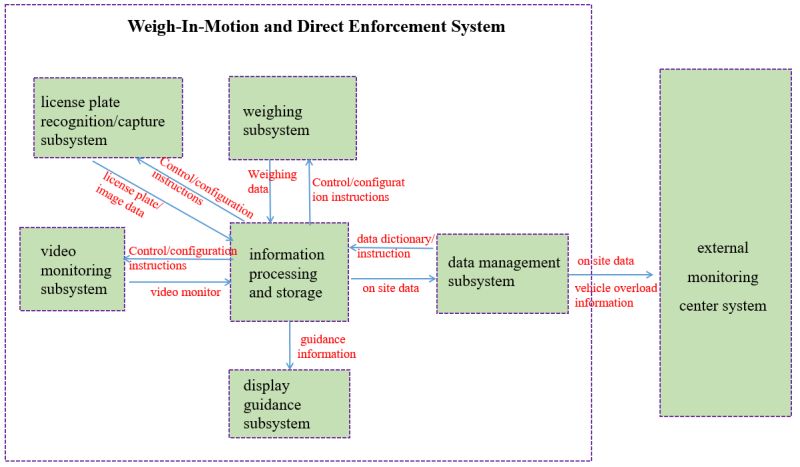
the internal and external interfaces relationship of the system
Internal interface design: there has 5 types of the direct enforcement system for vehicle overloading.
(1)Interface between weighing subsystem and information processing and storage subsystem
The interface between weighing subsystem and information processing and storage subsystem mainly deals with bidirectional data flow. The information processing and storage subsystem sends equipment control and configuration instructions to the weighing subsystem, and the weighing subsystem sends the measured vehicle axle weight and other information to the information processing and storage subsystem for processing.
(2)Interface between license plate recognition/capture subsystem and information processing and storage subsystem
The interface between the license plate recognition/capture subsystem and the information processing and storage subsystem mainly deals with bidirectional data flow. Among them, the information processing and storage subsystem sends device control and configuration instructions to the high-definition licenseplate recognition/capture subsystem, and the high-definition license plate recognition/capture subsystem sends the recognized vehicle license plate, license plate color, vehicle color and other data to the information processing and capture system for processing.
( 3 )Interface between video monitoring subsystem and information processing and storage subsystem
The interface between the video monitoring subsystem and the information processing and storage subsystem mainly deals with bidirectional data flow. The information processing and storage subsystem sends equipment control and configuration instructions to the video monitoring subsystem, and the video monitoring subsystem sends data such as law enforcement on-site video information to the information processing and storage subsystem for processing.
(4)Interface of Information display guidance subsystemwith Information Processing and Storage Subsystem
The interface between the information display guidancesubsystem with the information processing and storage subsystem mainly deals with one-way data flow. The information processing and storage subsystem sends data such as the license plate, load capacity, overweight and warning and guidance information of vehicles passing on the road to the information display guidance subsystem.
(5)Information Processing and Storage Subsystem and Data Management Subsystem Interface
The interface between the information processing and storage subsystem and the data management subsystem of the monitoring center mainly deals with bidirectional data flow. Among them, the data management subsystem sends basic data such as data dictionary and control instruction data of field equipment to the information processing and storage subsystem, and the data processing and storage subsystem sends the vehicle weight information, overload data packets, live video data and vehicle images, license plates and other data information collected on site to the data management subsystem.
External interface design
The vehicle overload direct enforcement system can synchronize the real-time data of the inspection site to other business processing platforms, and can also synchronize the vehicle overload information to the law enforcement system as the basis for law enforcement.

Enviko Technology Co.,Ltd
E-mail: info@enviko-tech.com
https://www.envikotech.com
Chengdu Office: No. 2004, Unit 1, Building 2, No. 158, Tianfu 4th Street, Hi-tech Zone, Chengdu
Hong Kong Office: 8F, Cheung Wang Building, 251 San Wui Street, Hong Kong
Factory: Building 36, Jinjialin Industrial Zone, Mianyang City, Sichuan Province
Post time: Mar-12-2024


